 | –≠–ª–µ–∫—Ç—Ä–æ–Ω–Ω—ã–π –∫–æ–º–ø–æ–Ω–µ–Ω—Ç: GS-R1012 | –°–∫–∞—á–∞—Ç—å:  PDF PDF  ZIP ZIP |
GS-R1012
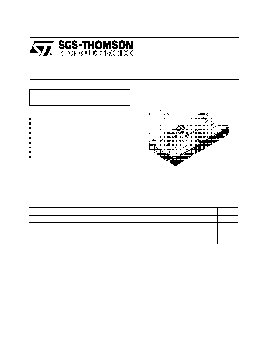
120W STEP-DOWN SWITCHING REGULATOR
June 1994
1/7
Type
V
i
V
o
I
o
GS-R1012
18 to 36 V
12 V
10 A
FEATURES
Wide input voltage range (18 to 36V)
High efficiency (90% min.)
Parallel operation with current sharing
Synchronization
Remote inhibit/enable
Remote load voltage sense
Output short-circuit protection
Soft-start
PCB or chassis mountable
DESCRIPTION
The GS-R1012 is a step-down switching voltage
regulator suitable to provide 12V/10A output volt-
age from a wide input voltage range (18 to 36V).
ABSOLUTE MAXIMUM RATINGS
Symbol
Parameter
Value
Unit
Vi
DC Input Voltage
40
V
Viinh
High Inhibit voltage
28
V
Tstg
Storage Temperature Range
≠ 20 to +105
∞
C
Tcop
Operating Case Temperature Range
0 to +75
∞
C
ELECTRICAL CHARACTERISTICS (T
amb
= 25
∞
C unless otherwise specified)
Symbol
Parameter
Test Conditions
Min
Typ
Max
Unit
Vi
Input Voltage
Vo = 12V
Io = 1.5 to 10A
18
24
36
V
li
Input Current
Vi = 24V
Io = 10A
5,6
A
lir
Reflected Input Current
Vi = 24V
Io = 10A
with external filter (C = 1000
µ
F)
400
500
mApp
Vien
Enable Input Voltage
Vi = 18 to 36V Io = 1.5 to 10A
0
1.2
V
Viinh
Inhibit Input Voltage
Vi = 18 to 36V Io = 1.5 to 10A
2
24
V
liinh
Inhibit Input Current
Vi = 18 to 36V Io =1.5 to 10A
Viinh = 5V
0.3
0.5
mA
Vo
Output Voltage
Vi = 18 to 36V Io = 1.5 to 10A
11.4
12
12.6
V
Vor
Output Ripple
Voltage
Vi = 24V
Io = 10A
150
mVpp
V
OL
Line Regulation
Vi = 18 to 36V Io = 10A
0.5
%
V
OO
Load Regulation
Vi = 24V
Io = 1.5 to 10A
1
%
Vo
Remote Sense
Compensation
Vi = 24V
Io = 10A
0.5
V
Io
Output Current
*
Vi = 18 to 36V
Vo = 12V
0
10
A
Iol
Output Current
Limiting
Vi = 18 to 36V
10.5
11.5
A
Iosc
Short-circuit Output
Current
Vi = 24V
16
A
Io
Current Sharing
Deviation
Vi = 24V
Io = 2 to 10A two modules in
parallel
10
%
tss
Soft-start Time
Vi = 24V
Io = 10A
15
ms
tr1
Line Transient
Recovery Time
Vi = 15 to 36V
Io = 5A
60
µ
s
tr2
Load Transient
Recovery Time
Vi = 24V
Io = 1.5 to 10A
100
µ
s
fs
Switching Frequency
Vi = 24V
Io = 1.5 to 10A
100
kHz
Efficiency
Vi = 18 to 36V
Io = 10A
90
92
%
Rthc
Thermal Resistance
Case-to-ambient
7.5
∞
C/W
*
Note: when output current is less than 1.5A, output ripple voltage increases due to discontinuous operation.
2/7
GS-R1012
3/7
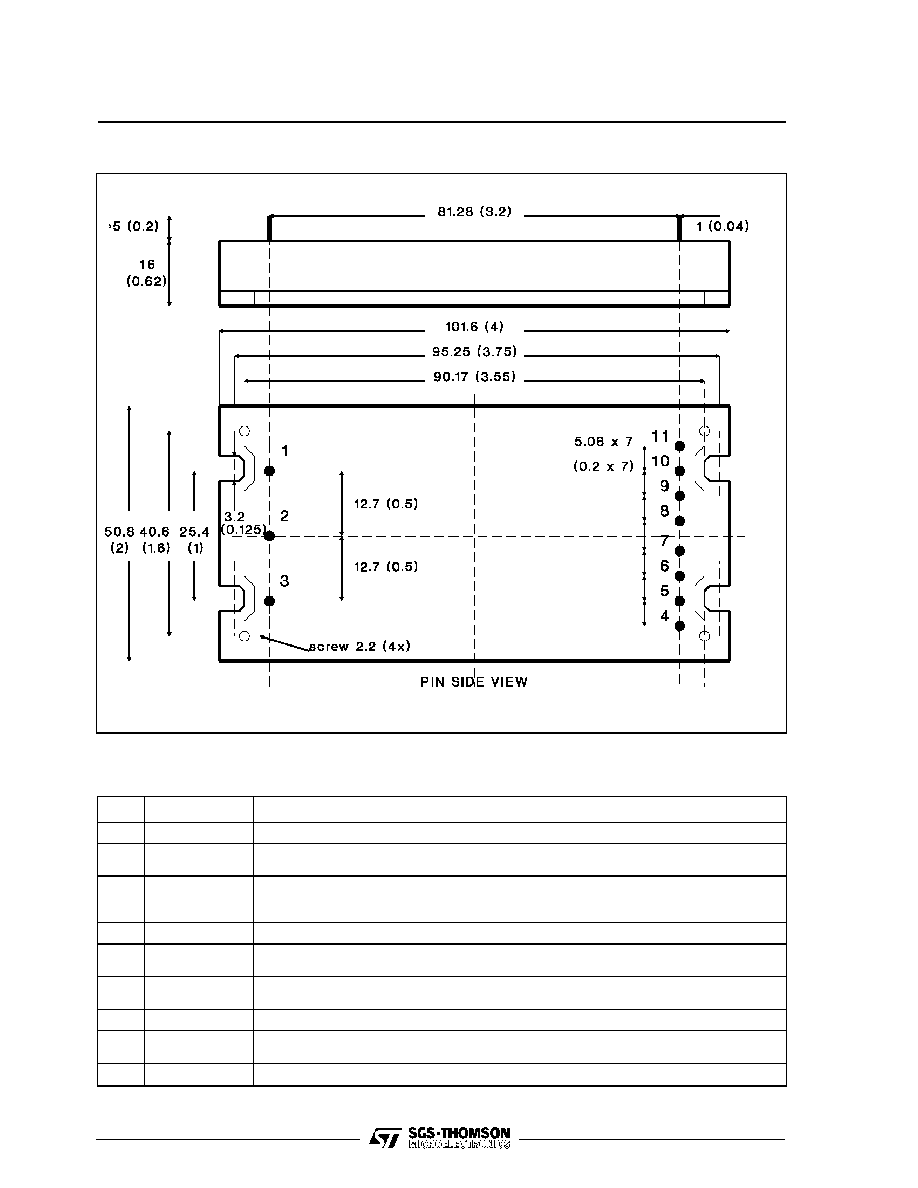
Dimensions in mm (inches).
CONNECTION DIAGRAM AND MECHANICAL DATA
PIN DESCRIPTION
Pin
Function
Description
1
GND Input
Return for input voltage source. Internally connected to pin 10,11.
2
Inhibit
The converter is ON (Enable) when this pin is unconnected or the voltage applied is lower
than 1.2V. The converter is OFF (Inhibit) for a control voltage in the range of 2 to 24V.
3
+ Vin
DC Input voltage; recommended maximum voltage is 36V.
External capacitor between pin 3 and pin 1 is mandatory; recommended value is
1000
µ
F/50V for switching application.
4,5
+ Vout
+12V output voltage.
6
+ Sense
Senses the remote load high side. To be connected to pin 4,5 when remote sense is not
used.
7
Sync
Synchronization output. See figures 1,2,3,4. Take care to leave the pin open when is not
used.
8
Parallel
Parallel output. See figures 1,2,3,4. Take care to leave the pin open when is not used.
9
- Sense
Senses the remote load return. To be connected to pin 10,11 when remote sense is not
used. In parallel configuration, take care to connect all -S pins together (see figures 1,2,3,4).
10,11
GND Output
Return for output current path. Internally connected to pin 1.
GS-R1012
4/7
USER NOTES
Input Voltage
The recommended operating maximum DC input
voltage is 36V inclusive of the ripple voltage. The
use of an external low ESR, high ripple current
capacitor located as close the module as possible
is mandatory; recommended value is 1000
µ
F/50V.
Softstart
To avoid heavy inrush current the output voltage
rise time is typically 15ms in any condition of load.
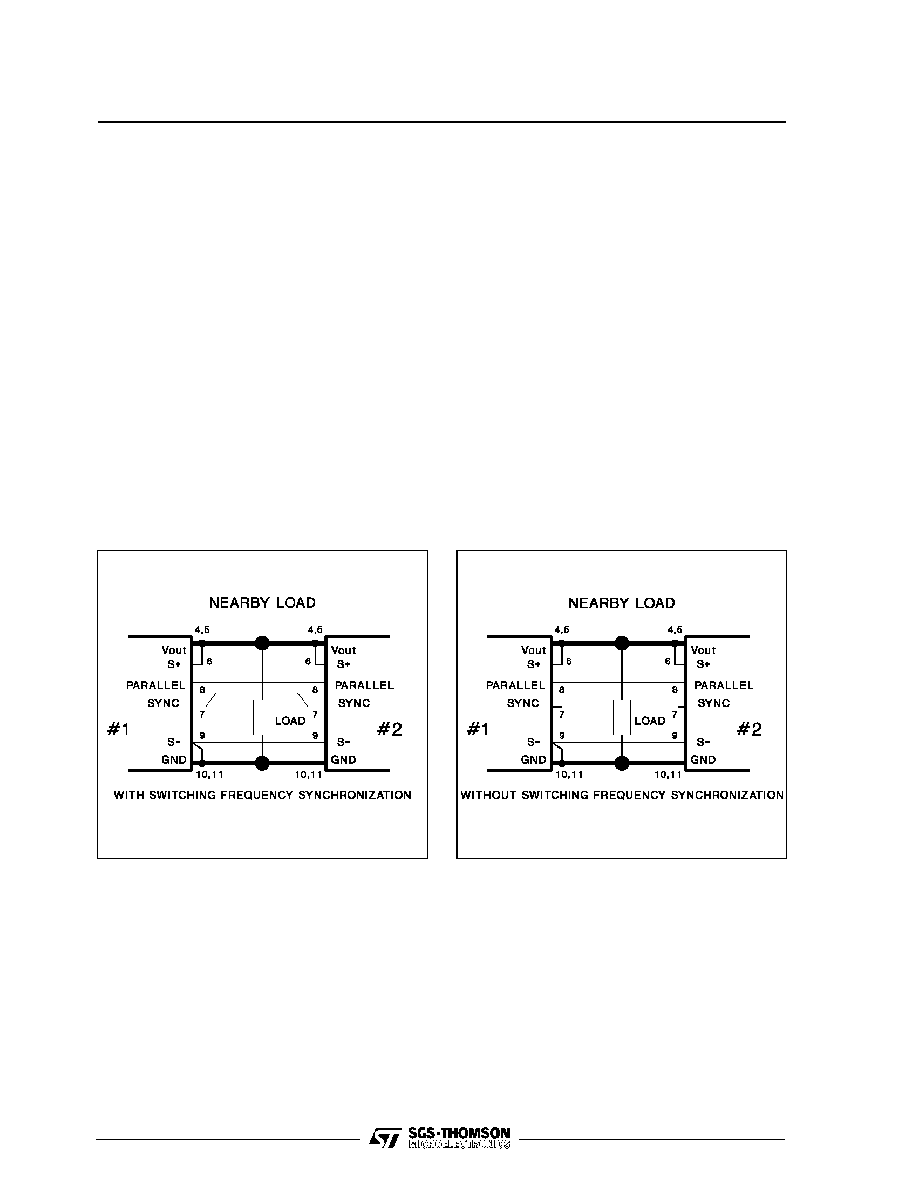
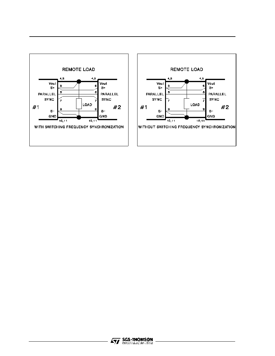
Remote Sensing
The remote voltage sense compensation range is
for a total drop of 500mV equally shared between
the load connecting wires. It is a good practice to
shield the sensing wires to avoid oscillations. See
the connection diagram on figures 1, 2, 3, 4.
Parallel Operation
To increase available output regulated power, the
module features the parallel connection possibility
with equal current sharing and maximum deviation
of 10% (two modules in parallel). See the connec-
tion diagram on figures 1, 2, 3, 4.
Module Protection
The module is protected against occasional and
permanent shortcircuits of the output pins to
ground, as well as against output current overload.
It uses a current limiting protection circuitry, avoid-
ing latch-up problems with certain types of loads.
Figure 1.
Figure 2.
GS-R1012
5/7
Thermal characterist ics: how to choose the
heat-sink
Sometimes the GS-R1012 requires an external
heat-sink depending both operating temperature
conditions and power.
Before entering into calculations details, some ba-
sic concepts will be explained to better understand
the problem.
The thermal resistance between two points is rep-
resented by their temperature difference in front of
a specified dissipated power, and it is expressed in
Degree Centigrade per Watt (
∞
C/W).
For GS-R1012 the thermal resistance case to am-
bient is 7.5
∞
C/W. This means that an internal power
dissipation of 1W will bring the case temperature at
7.5
∞
C above the ambient temperature.
The maximum case temperature to which the mod-
ule provides 10A is 75
∞
C (see fig. 6).
Let's suppose to have a GS-R1012 that delivers a
load current of 10A at an ambient temperature of
40
∞
C.
The dissipated power in this operating condition is
about 10.4W (at typical efficiency of 92%), and the
case temperature of the module will be:
T
Case
=
T
Amb
+
P
d
◊
R
th
=
40
+
10.4
◊
7.5
=
118
∞
C
This value exceeds the maximum allowed tempera-
ture and an external heat-sink must be added. To
this purpose four holes (see mechanical drawing)
are provided on the metal surface of the module.
To calculate this heat-sink, let's first determine what
the total thermal resistance should be.
R
th
=
T
CaseMAX
-
T
amb
P
d
=
75
-
40
10.4
=
3.37
∞
C / W
This value is the resulting value of the additional
heatsink thermal resistance.
Figure 3.
Figure 4.
GS-R1012