 | –≠–ª–µ–∫—Ç—Ä–æ–Ω–Ω—ã–π –∫–æ–º–ø–æ–Ω–µ–Ω—Ç: IMSB300-1 | –°–∫–∞—á–∞—Ç—å:  PDF PDF  ZIP ZIP |

TCPlink Development System
IMS B300
February 1996
42 1493 03
INMOS is a registered trademark of SGS-THOMSON Microelectronics Limited
1/12
FEATURES
DESCRIPTION
Compact desktop design, suitable for office or
computer room environments
Provides full interface to four independent net-
works over Ethernet
Uses TCP/IP protocol suite
Choice of single ended or differential link con-
nections
Independent diagnostics and test port simpli-
fies installation of software enhancements
LED activity indicators for each connection
The IMS B300 TCPlink box is a self-contained unit
providing four links and associated system ser-
vices for connection to target subsystems. The
four links are accessed over an Ethernet network
by host development computers running SGS≠
THOMSON Toolsets in conjunction with the TCP/
IP protocol suite. The unit supports the develop-
ment of programs in a network environment.
Diagnostic and monitoring facilities are provided
via a serial port on the IMS B300. This may be con-
nected to an ANSI compatible video terminal to
give interactive information displays on the unit's
operation.
Diagnostic
terminal
Ethernet
transceiver
Ethernet
cable
IMS B300
TCPLink
box
Differential sub-
system cables
(e.g. IMS CA15)
Single-ended
subsystem
cables
Subsys-
tem 3
Prototyping
system
AUI cable
ST20450
Development
Board
OS-Links

2/12
1
Overview
The IMS B300 is a complete fully cased sub-system unit that supports the development of applications in a networked
environment. Up to four target systems can be connected to the IMS B300. These can be connected up via differential
cables to a target with a differential interface, such as the ST20450 Development Board or via a single ended cable such
as the IMS CA16
.
The facilities can be shared amongst a larger group of development engineers and the use of network
connections avoids the need to install interface hardware within each type of workstation.
The IMS B300 contains a high performance multi-processor implementation of the TCP/IP protocol stack, giving a net-
work interface that is easily integrated into open-systems environments. A link service is offered over TCP connections
giving transparent access to four subsystem and link interfaces from a host based environment.
Multiple IMS B300 systems can be installed for larger development groups, with shared access facilities controlled using
a system of named link `capabilities'.
The status and configuration of each IMS B300 system can be examined and monitored using an attached serial terminal
which gives access to an interactive display capability. Front panel LEDs also give a continuous display of system activity.
2
Interfaces
2.1
Connection to Ethernet
The network connection provides an IEEE-802.3 AUI connection. This allows connections to either 10BASE-5,
10BASE-2 and 10BASE-T physical media via suitable `tap boxes'.
A standard IEEE 802.3 AUI cable should be used to connect the IMS B300 to an Ethernet transceiver. The cable should
be secured to the back panel connector using the slide lock provided. Suitable cables are available from transceiver ven-
dors.
2.2
Connection to diagnostic terminal
The serial port on the rear panel may be connected to an ANSI compatible video terminal to give interactive information
displays on the operation of the IMS B300. If this connection is not used, the IMS B300 will still operate as normal. Stan-
dard RS232 levels are used on the serial port (male 9-way D-type) which has a pin-out equivalent to that of an IBM PC
AT serial socket. The serial cable supplied with the IMS B300 works with VT220 and VT320 ASCII terminals and compa-
tibles or PCs running ASCII terminal emulation. The software on the IMS B300 programs the serial port to run at 9600
baud, 8 data bits, 1 stop bit, with XON/XOFF flow control. It is not necessary to use the hardware flow control lines (RTS
and DTS) provided on the connector. An example cable description for the terminal cable is given in Figure 1.
9≠way
female
D≠type
25≠way
female
D≠type
pin 2
pin 3
pin 5
pin 2
pin 3
pin 7
IMS B300
Terminal
Figure 1
Example cable connection to diagnostic terminal
2.3
Diagnostic functions
Diagnosis and monitoring of a `live' unit is achieved via a serial port on the IMS B300. This expects to communicate with
an ANSI compliant video terminal. A set of LEDs on the box front panel gives diagnostic information about the state of
each interface.

IMS B300 Ethernet connection system datasheet
3/12
One of the link connections has an associated services `Up' port which can be connected to an IMS B008 or similar board
in a PC. This allows field-service diagnosis of a dead unit which cannot boot-up from its own ROMs.
2.4
LED displays
The IMS B300 has seven front panel LED indicators. The right-most LED is the power indicator and should be illuminated
when powered up. The other six LED's are under software control. Full details of their functions are given in
[1].
3
Connecting the IMS B300 to a target network
The IMS B300 can have up to four separate networks connected to it which can be accessed individually through the
Ethernet. These networks can be interfaced to the IMS B300 in one of the following ways:
Single Ended
Differentially
The different methods can be intermixed with each other if required.
Each network interface consists of a set of three subsystem control signals and a pair of link connections.
If the noise on the connection rises above TTL signal noise margins, due to long cables or noisy environments, the signals
passing down the cable can be corrupted. Differential communications can be used to overcome both noise and earth
loop problems. They have a higher noise margin making them far less susceptible to noise. No common ground is re-
quired for differential signals so earth loop problems are also reduced.
A single-ended electrical connection usually provides the simplest and most convenient option. This is because TRAMs
and motherboards also use single-ended connections. However, in electrically noisy environments it is possible that
single-ended connections can suffer from data errors. Although in practice such errors are usually not observed, it is not
possible to ensure perfect error-free operation without using differential connections.
3.1
Connecting the IMS B300 to a differential target such as the ST20450 Development Board
For reliable operation in noisy environments, a differential cable should be used. Target systems such as the ST20450
Development Board [2] use a differential buffer to drive the OS-Link in addition to subsystem signals. A differential buffer
circuit such as the one used for the ST20450 Development Board is shown in Appendix A.
Physical connections are made using the 92CAB053 differential cable supplied with the ST20450 Development Board,
(order number ST20450-SAB/XXX). This cable is marked `Host' and `Target' at each end and should be connected
accordingly, i.e. `Host' connected to the IMS B300 and `Target' to the front panel differential connector on the ST20450
Development Board, as shown in figure 3. Jumper J3 on the development board should be configured in the `Front' posi-
tion as shown in figure 2.
Jumper J3
Front
Back
Figure 2
ST20450 Development Board J3 position

4/12
Dif
ferential cables
IMS B300
back panel
P2
ST20450 Development
Boards
Figure 3
Connection of four IMS B300 differential cables to ST20450 Development Boards
3.2
Using single ended connections via the IMS CA16 cables
A single-ended connection cable of type IMS CA16 can be used to connect the 26 way differential link connector to a
standard single ended OS-Link connector. The compact `D' type connector mates with one of the subsystem connectors
at the rear of the IMS B300. The other end terminates in three miniature M50 edge connector plugs polarised to match
standard link and subsystem cable conventions.
IMS B300 Ethernet connection system datasheet
5/12
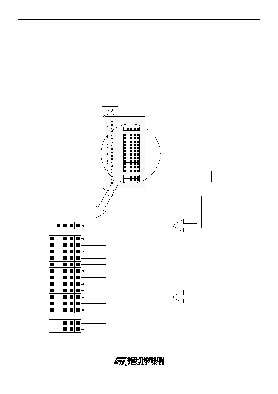
3.2.1
Connections to an IMS B014
The use of the IMS CA16 cable in conjunction with the connectors on a IMS B014 standard VME motherboard is illustrated
in figure 4. The jumper configuration of the motherboard is shown in figure 4. As can be seen, the single ended cable
connections from the IMS B300 are mated with a `breakout' connector or `hedgehog' mounted in the P4 front panel con-
nector of the IMS B014. A TRAM should be inserted in slot 0 of the IMS B014 motherboard array. Other TRAMs may
be added to the motherboard as required. The IMS B014 can be inserted in a VME rack or used in a bench-top mode
via a separate power supply.
Note that this example assumes the use of a 20Mbit/s link speed on both the IMS B300 subsystem and the IMS B014
motherboard. Also note that it is not possible to configure an IMS B014 to access the appropriate signal connections via
its back panel (P2) connector.
FrontServicesUp (on P4)
Link 0
Link 1
Link 2
Link 3
Link 4
Link 5
Link 6
Link 7
FrontConfigUp (on P4)
Connector Link (on P4)
not used
FrontConfigDown (P5)
not used
FrontServicesDown (on P5)
Link
From IMS B300
via IMS CA16 cable
SubsystemDown
Figure 4
Front panel `breakout' connector on P4 of IMS B014