 | –≠–ª–µ–∫—Ç—Ä–æ–Ω–Ω—ã–π –∫–æ–º–ø–æ–Ω–µ–Ω—Ç: L290B | –°–∫–∞—á–∞—Ç—å:  PDF PDF  ZIP ZIP |
L290
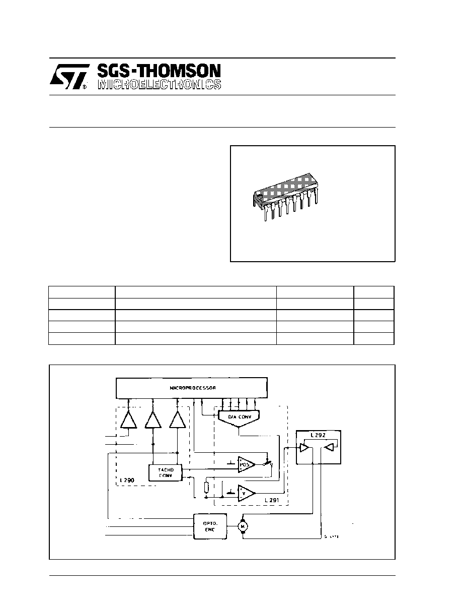
TACHOMETER CONVERTER
DESCRIPTION
The L290, a monolithic LSI circuit in 16-lead inline
plastic package, is intended for user with the L291
and L292 which together from a complete 3-chip
DC motor positioning system for applications
such as carriage/daisy-wheel position control in
typewriters.
The L290/1/2 system can be directly controlled by
a microprocessor. The L290 integrates the follow-
ing functions:
- tacho voltage generator (F/V converter)
- reference voltage generator
- position pulse generator
March 1993
Symbol
Parameter
Value
Unit
V
s
Supply Voltage
±
15
V
V
i
(FTA, FTB, FTF)
Input Signals
±
7
V
P
tot
Total Power Dissipation (T
amb
= 70
∞
C)
1
W
T
stg
, T
j
Storage and Junction Temperature
- 40 to + 150
∞
C
ABSOLUTE MAXIMUM RATING
SYSTEM BLOCK DIAGRAM
DIP-16 Plastic
(0.25)
ORDER CODE : L290B
1/8

BLOCK DIAGRAM
2/8
CONNECTION DIAGRAM (top view)
L290

Symbol
Parameter
Value
Unit
R
th-j-amb
Thermal resistance junction-case
Max
80
∞
C/W
THERMAL DATA
Symbol
Parameter
Test conditions
Min.
Typ.
Max.
Unit
V
s
Supply Voltage
±
10
±
15
V
I
d
Quiescent Drain Current
V
s
=
±
15 V
13
20
mA
INPUT AMPLIFIERS (A
1
and A
2
)
FTA, FTB
Input Signal from Encoder
(pin 1, 16)
f
max
= 20 KHz
±
0.4
±
0.6
V
p
V
os
Output Offset Voltage
(pin 2, 15)
FTA = FTB = 0 V
±
55
mV
I
b
Input Bias Current (pin 1, 16)
0.15
µ
A
G
v
Voltage Gain
f = 10 KHz FTA=
FTB =
±
0.6 V
p
22
23
24
dB
V
0
Output Voltage Swing
(pin 2, 15)
FTA = FTB =
±
1Vp
±
9.5
V
ELECTRICAL CHARACTERISTICS (Refer to the test circuit, S in (A), V
s
=
±
12 V, T
amb
= 25
∞
C
unless otherwise specified)
TEST CIRCUIT
3/8
L290

4/8
Symbol
Parameter
Test conditions
Min.
Typ.
Max.
Unit
COMPARATORS WITH HYSTERESIS (C
1
, C
2
, and C
3
)
V
THP
(
∞
)
Positive Threshold Voltage
(pin 2, 12, 15)
C
1
and C
2
550
850
mV
C
3
700
900
mV
V
THN
(
∞ ∞
)
Negative Threshold Voltage
(pin 2, 12, 15)
C
1
and C
2
55
175
mV
C
3
570
830
mV
FTF
Threshold Hysteresis
C
3
72
120
mV
V
L
Output Voltage (low level)
(pin 10, 13, 14)
I
0
= 2 mA
FTA = FTB = FTF = 0 V
0.2
0.4
V
I
leak
(pins 10, 13, 14)
FTA = FTB = 0.5 V
V
CE
= 5 V
FTF = 1 V
1
µ
A
REFERENCE GENERATOR
Vref
DC Reference Voltage
(pin 3)
FTA = FTB =
±
0.5 V
p
(*)
I
ref
= 1 mA
4.5
5
5.5
V
Iref
Output Current (pin 3)
1.4
mA
"TACHO" AMPLIFIER (A3)
V
os
Output Offset Voltage (pin 4)
FTA =
±
15 mV
FTB = 0.5V
±
80
mV
V
o
DC Output Voltage (pin 4)
FTA = FTB =
±
0.5 V
p
(**)
V
01
5.4
6
6.6
V
VMA = VMB =
±
1.25 V
p
(***)
V
02
- 5.4
- 6
- 6.6
V
0
V
01
+ V
02
- 150
+ 150
mV
V
0
Output Voltage Swing (pin 4)
FTA = FTB = 0.5V
9
V
Sin (B)
FTA = FTB = -0.5 V
- 9
V
MA
V
MB
Multiplier Input Voltage
(pin 7, 8)
±
1.25
±
1.7
V
p
V
bias
Bias Voltage (pin 6)
FTA and FTB Floating
- 6.5
- 8
V
ELECTRICAL CHARACTERISTICS (continued)
(
∞
)
:
FTA = FTB = FTF
(
∞ ∞
)
: FTA= FTB = FTF =
Note
:
Phase relationship between the signals :
* FTA : 0
∞
FTB : 90
∞
** FTA : 0
∞
FTB : - 90
∞
V
MA
= 90
∞
V
MB
= 0
∞
*** FTA : 0
∞
FTB : 90
∞
V
MA
= 90
∞
V
MB
= 180
∞
0
1V
0
1V
L290

WAVEFORMS (Neglecting threshold volage level of the comparators).
SYSTEM DESCRIPTION : refer to the L292 data sheet.
5/8
L290