December 1999
L4620
LIQUID LEVEL ALARM
.
DRIVES DIRECTLY 300 mA ALARM LOAD
.
PROGRAMMABLE INPUT POLARITY TO
ACTIVATE THE OUTPUT STAGE
.
PROGRAMMABLE DELAY TIME
.
PROGRAMMABLE OUTPUT DUTY CYCLE
.
OUTPUT SHORT CIRCUIT PROTECTION
.
OVERVOLTAGE AND THERMAL
PROTECTION
DESCRIPTION
The L4620 is an integrated circuit, designed for the
liquid level control in automotive applications. The
liquid level is indicated by an attenuation between
transmitted and received signal across a sensor tip
in the lquid. If the attenuation exceedes an internal
threshold- sensortip outside the liquid or liquid tem-
peraturehigher than a determined value - a square-
wave alarm output indicates an unsufficient liquid
condition.If the liquid level is restoredbeforethe end
of a delay time the alarm is not activated.
Throughtwo pins it is possible to program : the delay
time to activate the alarm, the duty cycle of the
output squarewave, the polarity of the input thre-
shold of the sensor for alarm activation.
The above featuresmake theL4620particularlyver-
satile for many applications and give the possibility
to use various sensor types.
Internal circuits prevent spurious indications from
the liquid sensor and a latch keeps the alarm acti-
vateduntilthe supply voltageis switchedoff.The de-
vice includes thermal shutdown protections.
Minidip
ORDERING NUMBER : L4620
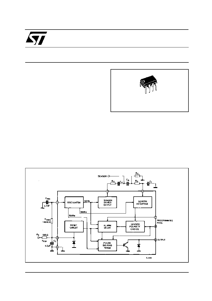
BLOCK DIAGRAM
�
1/9

ABSOLUTE MAXIMUM RATINGS
Symbol
Parameter
Value
Unit
I
S
Supply Current (V
S
> V
Z
)
200
mA
V
3
Sensor Input Voltage (V
2
High)
7
V
I
out
Output Current
500
mA
P
tot
Power Dissipation at T
amb
= 70
�
C
0.8
W
T
j
, T
stg
Junction and Storage Temperature Range
� 55 to 150
�
C
PIN CONNECTION (top view)
THERMAL DATA
Symbol
Parameter
Value
Unit
R
th j-amb
Thermal Resistance Junction-ambient
Max
100
�
C/W
L4620
2/9

PIN FUNCTION (Block Diagram)
N
�
Name
Function
1
Oscillator
A capacitor C
osc
connected to ground and a resistor R
osc
connected to pin 5 (supply
voltage) set the frequency of the internal oscillator. The period is given by: T
osc
= 0.693
(R
osc
+ 5000) C
osc
2
Sensor Output
A squarewave is available at this pin to drive the external sensor. The output
frequency is 1/32 of the internal oscillator fosc, i.e. 50Hz using the values of
R
osc
= 180k
and C
osc
= 4.7nF for the external components.
3
Sensor Input
Connection for liquid level sensing. During the zero level of the squarewave signal at
pin 2, the internal sensing circuit is disabled. During the high level of the wave shape
the input is compared with a threshold which depends on the output sensor volta
V
SENSH
= 0.4V
2
(typ). If the input voltage becomes higher than the above V
SENSH
, the
V
sens
value is reduced to V
SENSL
= 0.22V
2
(typ), providing an hysteresis available with
both the programmable polarities.
4
GND
This pin must be connected to ground.
5
Supply Voltage
Supply voltage input. A 4.5V (typical) zener is present at the input. The external
resistor limits the current through the zener for high supply voltages. Moreover when
the voltage at this pin is down 2.5V (typical) the internal reset circuit is activated
6
Alarm Driver
Output
An internal open collector stage is available at this pin to drive the external alarm
indicator by a rectangular waveshape. The output period depends on the external
component R
osc
and C
osc
. Using the recommended values of block diagram th
7
Alarm Delay
Select
This program pin selects the alarm delay to activate the output stage after a low liquid
level indication of the sensor. The delay depends on the internal oscillator frequency.
Refer to application circuit, if this pin is kept low the typical delay is 10.
8
Sensor Polarity
Select Output
Duty-cycle
Select
Through this pin it is possible to program both the sensor polarity with respect to the
internal threshold and the duty-cycle of the output waveform which drives the alarm.
When this pin is kept low the output rectangular wave duty cycle is 1:64
(T = 320ms, t = 5ms in fig. 2) and the output is activated, after the delay time, if the
voltage at pin 3 is higher than V
SENS
. When the voltage at this pin is high the output
duty cycle is 50% (t = 160ms) and the output goes on, after the delay
L4620
3/9

1
*) This is a squarewave signal. The frequency is given by : f =
f
osc
.
32
1
**) The output squarewave signal frequency is given by f =
fosc.
512
The duty cycle depends on the state of the pin 8 and can be or 1 : 2 or 1 : 64, i.e. refer to figure 2, T = 320 ms, t = 160 or 5 ms when
the oscillator frequency f
osc
= 1.6 KHz.
ELECTRICAL CHARACTERISTICS (T
amb
= 25
�
C, unless otherwise specified. Refer to block diagram
for external component values)
Symbol
Parameter
Test Conditions
Min.
Typ.
Max.
Unit
V
Z
Internal Zener Voltage (pin 5)
I
S
= 24 mA
4
4.5
5
V
I
S
Supply Current (pin 5)
V
S
= 3.8 V
6.5
11
mA
f
osc
Oscillator Frequency (pin 1)
R
osc
= 180 k
, C
osc
= 4.7 nF
1.45
1.6
1.75
kHz
V
7
, V
8
Programming Pins Input
Voltage (pin 7, 8)
Low State
0.3
V
High state
2
V
I
7
, I
8
Programming Pins Input Current
(pin 7, 8)
V
7
= V
8
= 0 V
� 1
�
A
V
7
= V
8
= V
Z
150
�
A
V
2
Sensor Drive Output Voltage, (*) V
2
= Low,
I
2
= 1 mA
0.4
V
V
2
= High,
I
2
= 1 mA
V
Z
�1
V
Z
�0.4
V
I
2
Sensor Driver Output Current
� 1
1
mA
V
SENSH
/V
2
Sensor Input High Threshold
Voltage Versus V
2
(pin 3)
V
2
= High
V
pin 3
< V
SENSL
0.33
0.4
0.47
V
sens
_____
V
2
Sensor Input Low Threshold
Voltage Versus V
2
(pin 3)
V
2
= High
V
pin 3
> V
SENSH
0.15
0.22
0.29
V
clamp3L
Sensor Input Clamping Voltage
(pin 3)
� 100
�
A < I
sens
< 100
�
A
V
2
= Low
� 0.1
0.1
V
V
clamp3H
V
2
= High
I
3
= � 100
�
A
� 0.8
� 0.6
� 0.4
V
I
3
= + 100
�
A
V
Z
V
Z
+0.8
V
I
sens
Sensor Input Bias Current (pin
3)
V
sens
= High
1.2
�
A
T
d
Delay Time
f
osc
= 1.6 kHz
V
7
= Low
10.24
sec
V
7
= High
20.48
sec
V
out(sat)
Output Stage Saturation
Voltage (pin 6) (**)
I
out
= 200 mA
1.3
V
V
out(clamp)
Output Stage Overvoltage
Protection (pin 6)
I
out
= 70 mA
19
21
23
V
I
LEAK
Leak Current (pin 6)
P6 = 15V; P7 = P8 = GND
100
�
A
L4620
4/9

The L4620 liquid level alarm is designed to operate
with a variety of sensor types which change imped-
ance depending on whether the sensor is above or
below the level of a liquid. If the impedancevariation
of ther liquid itself is sensed, a very simple sensor
(two electrodes) can be used. The output stage
drives directly the alarm indicator with a 300mArec-
tangular wave signal, the duty cycle of which is pro-
grammable.
SENSOR INTERFACE.
As shownin the applicationcircuit, the sensoris con-
nected so that it varies the attenuation of a square-
wave signal between pin 2 and pin 3 where its posi-
tive half cycle is comparedwiththe referencethresh-
old (with hysteresis).
This frequency, generated internally by a 50% duty
cycle oscillator, is 50Hz in the typical application
(R
osc
= 180K
C
osc
= 4.7nF).
The threshold of the sensor input is a function of the
outputvoltageat pin 2. The hysteresisis provided by
a Schmitt trigger comparator. As shown in figure 1,
this gives hysteresis with either threshold polarity
selected.
The AC driving of the level sensor allows the use of
a capacitive filter (C
A
, C
B
, C
C
in block diagram)
which acts as a bandpass filter at the frequency
used.The resistor R
C
in theapplicationcircuit biases
the sensor input stage. In this way the interference
problems typical of automotive applications are re-
duced considerably. If, however, it is not necessary
to decouple and filter the sensor a simple resistive
network may be used, eliminating the capacitors.
SPURIOUS INDICATION PROTECTION.
To preventspurious alarm signals when the liquid is
agitated or in the presence of interference, the de-
vice includes two protection mechanism :
Firstly, the sensor interface which samples the posi-
tive halfcycleof the sensor signalactivatesits output
only if there are four consecutive alarm conditionin-
dications. Secondly, the alarm output stage is only
activated after an externally programmable delay.
During this delay if the alarm condition ceases the
alarm output will not be activated.
Using the values C
osc
= 4.7nF and R
osc
= 180K
,
which give a typical oscillator frequency of 1.6KHz,
delaysof about 10 s (programmingpin 7 low)or 20s.
INTERNAL MEMORY.
When the alarm output has been activated an inter-
nal latch holds it in the active state until the power
supply is removed. This feature ensures that the
alarm will not be interrupted if the sensor connection
breaks.
OUTPUT STAGE.
Throughpin 8 it is possibleto programthe duty cycle
of the alarm signal waveform (see figure 2). When
pin 8is high the outputsignal has a dutycycle of 50%
; if pin 8 is low the duty cycle is 1 : 64. The period of
the output signal is always 320ms using the compo-
nent values indicated in block diagram.
The outputstagecan deliver up to 300mAand is pro-
tected internally against overvoltages (by a zener).
A thermal shutdown circuit provides additional pro-
tection.
CIRCUIT OPERATION
L4620
5/9