 | –≠–ª–µ–∫—Ç—Ä–æ–Ω–Ω—ã–π –∫–æ–º–ø–æ–Ω–µ–Ω—Ç: L9444VB | –°–∫–∞—á–∞—Ç—å:  PDF PDF  ZIP ZIP |
L9444VB/L9448VB
L9480VB
ONE CHIP CAR ALTERNATOR REGULATOR
ADVANCE DATA
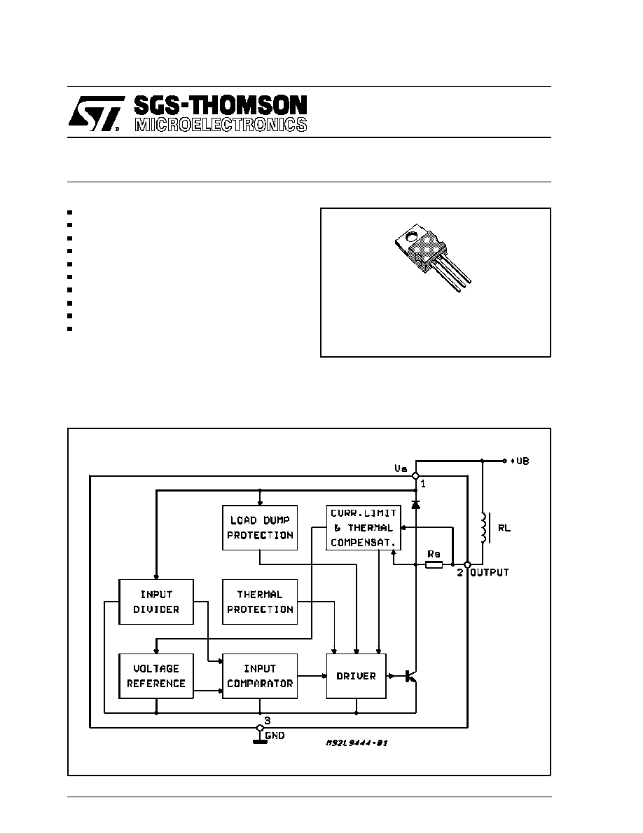
NO EXTERNAL COMPONENTS
PRECISE TEMPERATURE COEFFICIENT
PRECISE REGULATED VOLTAGE
HIGH OUTPUT CURRENT
SHORT CIRCUIT PROTECTED
REVERSE BATTERY PROTECTION
+ 80 V LOAD DUMP PROTECTION
LOW ENERGY SPIKE PROTECTION
THERMAL SHUTDOWN
VERY LOW START UP VOLTAGE
DESCRIPTION
The devices are a "single function" self-oscillating
voltage regulator for car alternators. Integrating
both the control section and the output power
stage on a single chip, the devices require no ex-
ternal components, reducing significantly the cost
of the system and increasing reliability.
This is advanced information on a new product now in development or undergoing evaluation. Details are subject to change without notice.
October 1992
BLOCK DIAGRAM
TO220
ORDERING NUMBER: L9444VB
L9448VB
L9480VB
1/5
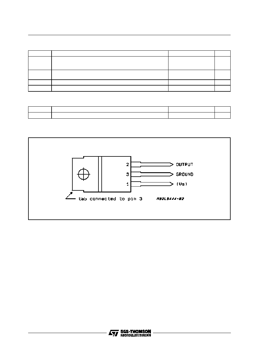
PIN CONNECTION (top view)
ABSOLUTE MAXIMUM RATINGS
Symbol
Parameter
Value
Unit
V
S
Transient Overvoltage :
Load Dump : 5ms
T
rise
10ms,
f
Fall Time Constant
100ms, R
source
0.5
80
V
I
clamp
Current into Low Energy Clamping Zener
(T
rise
= 5
µ
s ; T
decay
2ms ; duty cycle
5%)
100
mA
I
out
Maximum Output Current
5.5
A
T
j
, T
stg
Junction and Storage Temperature Range
≠ 55 to + 150
∞
C
THERMAL DATA
Symbol
Parameter
Value
Unit
R
th i-case
Thermal Resistance Junction-case
Max.
3
∞
C/W
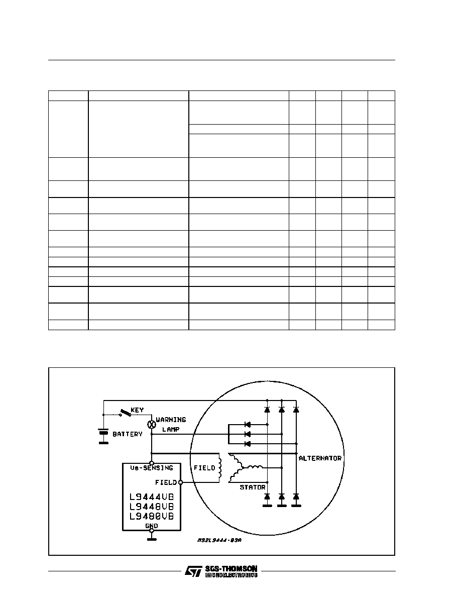
DEVICE OPERATION
The alternator voltage, rectified by the auxiliary di-
ode trio, is compared with an external reference
and the resulting signal switches the output stage,
driving the alternator field coil.
As the regulator is a self-oscillating type, the
switching frequency depends on the whole sys-
tem parameter set (including the alternator char-
acteristics).
The regulator has an integrated filter in the volt-
age sensing path. Consequently it doesn't need -
in the standard application- any external compo-
nent.
Anyway an external capacitor (0.1 - 1
µ
F) must be
inserted between V
S
and Ground guaranteeing
the correct behaviour of the device when the rec-
tifying diodes feature very high switching spikes
that are not filtered by the devices.
This external capacitor must also be used when
the impedances of the cables connecting the al-
ternator to the battery are so high to cause a su-
perimposed ripple on the alternator voltage higher
than 3-4V.
The devices regulation voltage and the tempera-
ture coefficient may be independently set by
suited metal mask selections ; furthermore the
regulation voltage is trimmed within
±
1% of the
nominal value @ 25
∞
C.
The devices have an unique -and patented- sys-
tem to compensate the self-heating of the die due
to the power dissipated in the output stage. In this
way the internal reference voltage tracks the case
temperature rather than the die one.
The device can withstand the reverse battery and
the load dump (up to 80V) ; They can absorb, into
the internal clamping zeners, low energy spikes
up to a level of 100mA and its output is short cir-
cuit protected.
Finally the internal thermal shutdown avoids any
possible device damage due to overtemperature
problems.
L9444VB -L9448VB - L9480VB
2/5
ELECTRICAL CHARACTERISTICS (≠ 40
∞
C
T
J
125
∞
C unless otherwise noted)
Symbol
Parameter
Test Conditions
Min.
Typ.
Max.
Unit
V
r
Regulation Voltage
T
j
= ≠40
∞
C
for L9444VB
for L9448VB
for L9480VB
14.49
14.36
14.75
14.79
14.66
15.05
15.05
14.96
15.35
V
V
V
T
j
= 25
∞
C
14.10
14.40
14.70
V
T
j
= 125
∞
C
for L9444VB
for L9448VB
for L9480VB
13.50
13.70
13.10
13.80
14.00
13.40
14.10
14.30
13.70
V
V
V
C
T
Temperature Coeff. of the
Regulation Voltage
for L9444VB
for L9448VB
for L9480VB
- 6
- 4
- 10
mV/
∞
C
mV/
∞
C
mV/
∞
C
eC
T
Error on Nominal Temperature
Coeff.
±
30
%
V
r
Load Regualtion
0.1 I
n
< I
alt
< 0.9 I
n
(note 1)
250
mV
V
su
Control Circuit Minimum Start
up Voltage
Measured at Supply Pin
2
3
V
V
sd
Shutdown Voltage (dump
protection threshold)
22
V
V
sat 1
Output Saturation Voltage
I
field
= 4 A
p
1.2
2
V
V
sat 2
Start Up Saturation Voltage
I
field
= 200 mA
0.7
1
V
I
q
Quiescent Current
Field Off
20
mA
I
s
Supply Current
I
field
= 4 A
p
50
mA
I
fs
Field Pin Sink Current
Field Off
Field Pin @ 16 V
5
mA
V
1 CLAMP
Low Energy Clamping Zener
Voltage
I
clamp
= 50 mA
120
V
f
sw
Switching Frequency
01 I
n
< I
alt
< 0.9 I
n
30
1000
Hz
Note1: measured on an alternator with the following characteristics: I
n
=<90A; I
alt
/I
field
>= 23
APPLICATION CIRCUIT
L9444VB - L9448VB - L9480VB
3/5
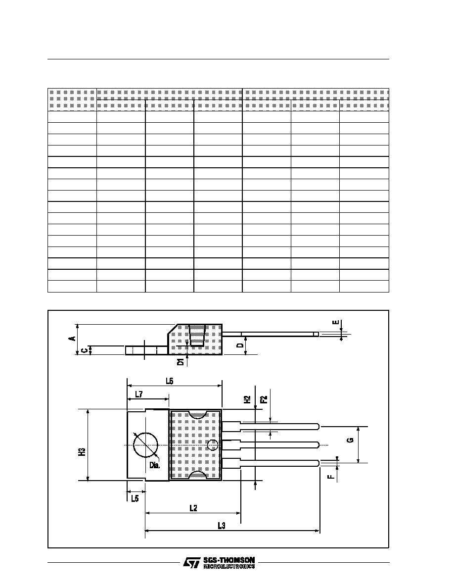
TO220 PACKAGE MECHANICAL DATA
DIM.
mm
inch
MIN.
TYP.
MAX.
MIN.
TYP.
MAX.
A
4.8
0.189
C
1.37
0.054
D
2.4
2.8
0.094
0.110
D1
1.2
1.35
0.047
0.053
E
0.35
0.55
0.014
0.022
F
0.8
1.05
0.031
0.041
F2
1.15
1.4
0.045
0.055
G
4.95
5.08
5.21
0.195
0.200
0.205
H2
10.4
0.409
H3
10.05
10.4
0.396
0.409
L2
16.2
0.638
L3
26.3
26.7
27.1
1.035
1.051
1.067
L5
2.6
3
0.102
0.118
L6
15.1
15.8
0.594
0.622
L7
6
6.6
0.236
0.260
Dia
3.65
3.85
0.144
0.152
L9444VB -L9448VB - L9480VB
4/5

Information furnished is believed to be accurate and reliable. However, SGS-THOMSON Microelectronics assumes no responsibility for the
consequences of use of such information nor for any infringement of patents or other rights of third parties which may result from its use. No
license is granted by implication or otherwise under any patent or patent rights of SGS-THOMSON Microelectronics. Specifications men-
tioned in this publication are subject to change without notice. This publication supersedes and replaces all information previously supplied.
SGS-THOMSON Microelectronics products are not authorized for use as critical components in life support devices or systems without ex-
press written approval of SGS-THOMSON Microelectronics.
©
1994 SGS-THOMSON Microelectronics - All Rights Reserved
SGS-THOMSON Microelectronics GROUP OF COMPANIES
Australia - Brazil - France - Germany - Hong Kong - Italy - Japan - Korea - Malaysia - Malta - Morocco - The Netherlands - Singapore -
Spain - Sweden - Switzerland - Taiwan - Thaliand - United Kingdom - U.S.A.
L9444VB - L9448VB - L9480VB
5/5