L9820
HIGH SIDE DRIVER
ADVANCE DATA
OPERATING SUPPLY VOLTAGE UP TO 25V
DC CURRENT 0.3A
R
ON
< 800m
DIAGNOSTIC AND PROTECTION FUNC-
TIONS
µ
P COMPATIBLE
ENABLE INPUT FOR STAND-BY MODE
DESCRIPTION
The L9820 High Side Driver realized with Mul-
tipower - BCD mixed technology, drives resistive
or inductive loads with one side connected to
ground.
The ENABLE input is TTL compatible and a diag-
nostic output provides an indication of short circuit
and device status (thermal and overvoltage shut-
down). Onchip thermal protection and short circuit
protection are provided.
This is advanced information on a new product now in development or undergoing evaluation. Details are subject to change without notice.
February 1994
BLOCK DIAGRAM
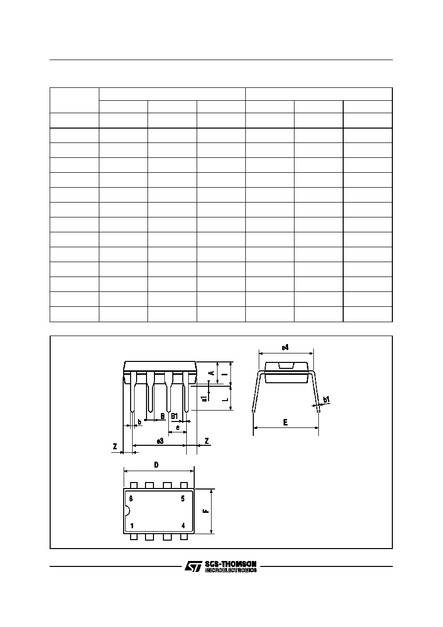
Minidip
SO8
ORDERING NUMBERS:
L9820
L9820D
MULTIPOWER BCD TECHNOLOGY
40m
1/6

ABSOLUTE MAXIMUM RATINGS
Symbol
Parameter
Value
Unit
V
S
Max Forward Voltage
50
Vdc
I
R
Reverse Bias Current at -1.3V
≠0.46
A
V
5
Input Voltage (to GND)
≠0.3 to 20
V
V
8
Diag. Output Voltage (to GND)
≠0.3 to 20
V
V
1
Output Voltage (to GND)
≠0.3 to 25
V
I
4
Supply Current
Internally limited
I
5
Enable Input Current
0.5
mA
I
8
Diag. Out Current (sink)
10
mA
I
1
Output Current
Internally limited
T
op
Operation Temperature
≠40 to 85
∞
C
T
j
, T
stg
Junction and Storage Temperature Range
≠55 to 150
∞
C
T
jp
Detecting Temperature
150
∞
C
THERMAL DATA
Symbol
Parameter
Minidip
SO8
Unit
R
th j-amb
Thermal Resistance Junction-ambient
Max.
100
200
∞
C/W
TRUTH TABLE
H: high level
L: low level
ENABLE
FUNCTION
DIAG. STATUS
POWER STATUS
L
Operating OFF
H
L
H
Normal Operation
H
H
H
Overvoltage Protection ON
L
L
H
Overcurrent Protection ON
L
L
H
Overtemperature
Protection ON
L
L
PIN CONNECTION (Top views)
Minidip
SO8
L9820
2/6

PIN FUNCTIONS
N.
Name
Description
1
POWER OUTPUT
The device is provided with short circuit protection.
4
POWER SUPPLY
Supply voltage input.
5
ENABLE INPUT
TTL compatible input. High level on this pin means output current ON.
The low level voltage switches off the charge pump, the power stage and
the diagnostic output reducing to the minimum value the quiescent current.
7
GROUND
This pin must be connected to ground.
8
DIAGNOSTIC FEEDBACK
The diagnostic circuit is active in input high level condition. This output
detects with Tipically 50
µ
s delay at T
amb
= 25
∞
C the following faults:
≠ Overvoltage condition.
≠ Thermal shutdown.
≠ Short circuit. The power stage current is internally limited at 1.5A.
The diagnostic output is active low. The diagnostic delay time allows to
avoid spurious diagnosys(i.e.: turn ON overcurrent, overvoltage spikes etc.).
ELECTRICAL CHARACTERISTICS (V
S
= 14.4V, ≠40
∞
C
T
j
+85
∞
C, unless otherwise specified.)
Symbol
Parameter
Test Condition
Min.
Typ.
Max.
Unit
V
S
Operating Supply Voltage
6
25
V
R
on
On Resistance
Input > 2V, T
j
= 25
∞
C
Input > 2V, Full T range
0.6
0.8
1.2
I
off
Off State Supply Current
T
j
< 35
∞
C
T
j
= 85
∞
C
130
300
µ
A
µ
A
I
on
On State Supply Current
4
mA
V
EL
Enable Low Level
0.8
V
V
EH
Enable High Level
2
V
I
E
Enable Current
0V < Vi <5V
10
µ
A
I
leakd
Diagnostic Output Leakage Current
V
CC
= 5V Diagnostic Output High
10
µ
A
V
sat d
Diagnostic Output Saturated
Voltage
Isink < 3.5mA
0.4
V
t
dd
Diagnostic Delay Time
T
j
= 25
∞
C
30
µ
s
t
don
Output ON Delay Time
T
j
= 25
∞
C
30
µ
s
t
r
Output ON Rise Time
Tj = 25
∞
C
100
µ
s
t
doff
Output OFF Delay Time
Tj = 25
∞
C
80
µ
s
t
f
Output OFF Fall Time
Tj = 25
∞
C
100
µ
s
V
don
Overvoltage Detection ON
25
V
V
dh
Overvoltage Hysteresis
2
5
V
I
don
Overcurrent Detection ON
0.5
1.5
A
T
don
Overtemperature Detection ON
150
∞
C
T
dh
Overtemperature Hysteresis
25
50
∞
C
L9820
3/6