 | –≠–ª–µ–∫—Ç—Ä–æ–Ω–Ω—ã–π –∫–æ–º–ø–æ–Ω–µ–Ω—Ç: LM223K | –°–∫–∞—á–∞—Ç—å:  PDF PDF  ZIP ZIP |
1/10
February 2003
s
OUTPUT CURRENT: 3A
s
INTERNAL CURRENT AND THERMAL
LIMITING
s
TYPICAL OUTPUT IMPEDANCE: 0.01
s
MINIMUM INPUT VOLTAGE: 7.5V
s
POWER DISSIPATION: 30W
DESCRIPTION
The LM123, LM223, LM323 are three-terminal
positive voltage regulators with a preset 5V output
and a load driving capability of 3A. New circuit
design and processing techniques are used to
provide the high output current without sacrificing
the regulation characteristics of lower current
devices.
The 3A regulator is virtually blowout proof.
Current limiting, power limiting and thermal
shut-down provide the same high level of reliability
obtained with these techniques in the LM209, 1A
regulator. An overall worst case specification for
the combined effects of input voltage, load
current,
ambient
temperature,
and
power
dissipation ensure that the LM123, LM223, LM323
will perform satisfactorily as a system element.
LM123/LM223
LM323
THREE-TERMINAL 3A-5V
POSITIVE VOLTAGE REGULATORS
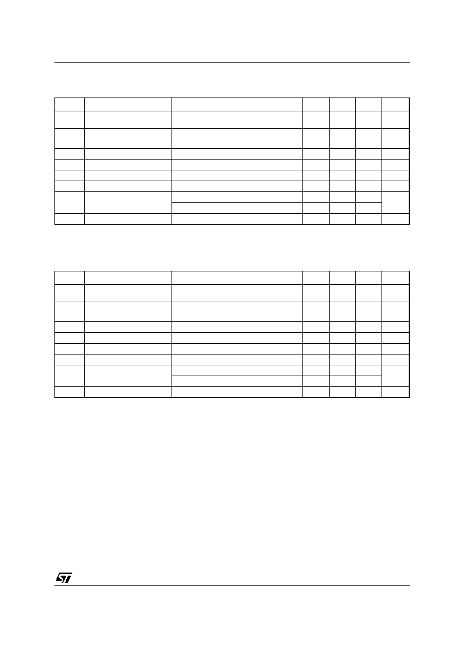
SCHEMATIC DIAGRAM
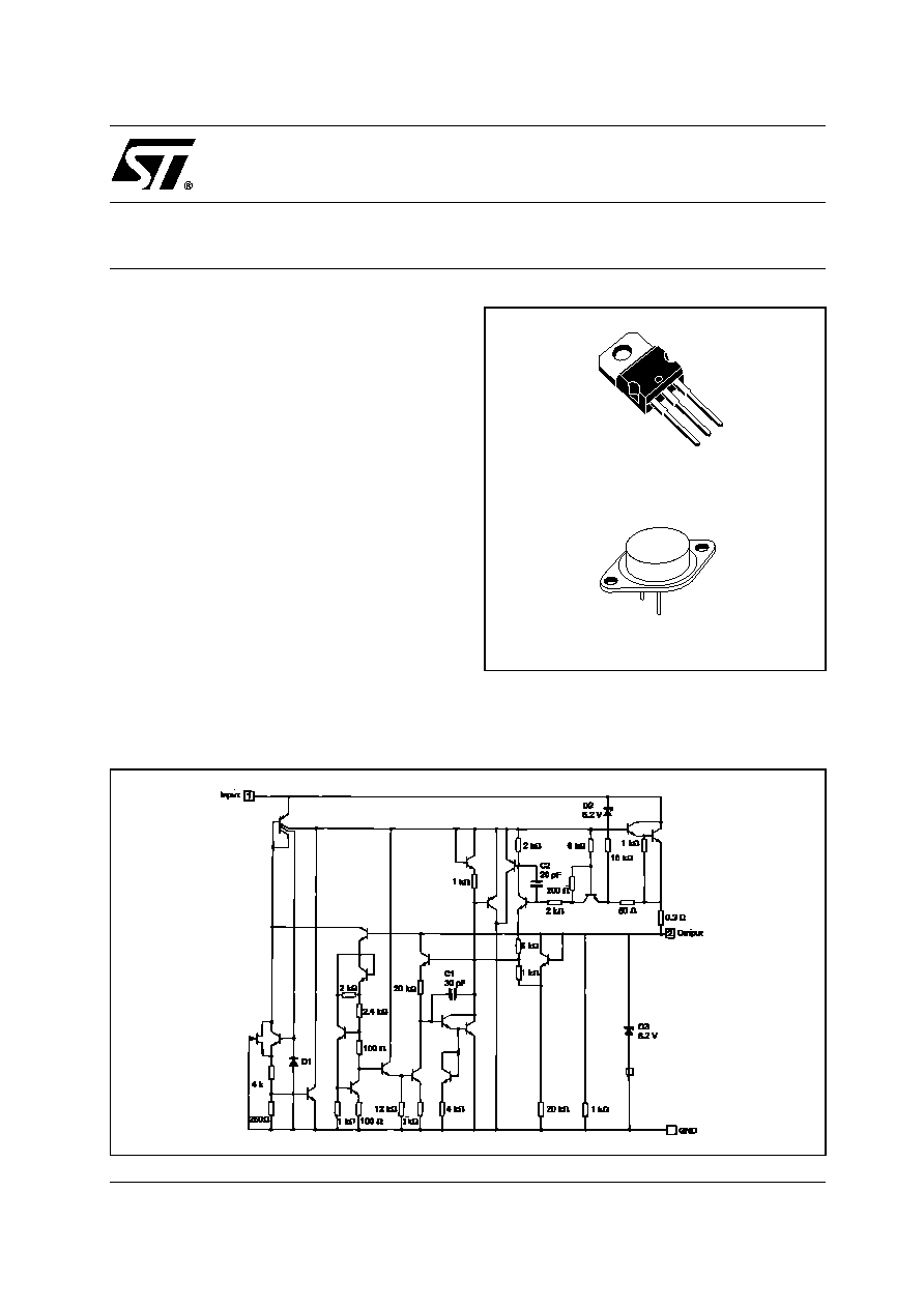
TO-220
TO-3

LM123-LM223-LM323
2/10
ABSOLUTE MAXIMUM RATINGS
Absolute Maximum Ratings are those values beyond which damage to the device may occur. Functional operation under these condition is
not implied.
THERMAL DATA
CONNECTION DIAGRAM (top view)
ORDERING CODES
Symbol
Parameter≤
Value
Unit
V
I
Input Voltage
20
V
I
O
Output Current
Internally Limited
P
tot
Power Dissipation
Internally Limited
T
stg
Storage Temperature Range
-65 to 150
∞C
T
oper
Operating Junction Temperature Range
LM123
-55 to 150
∞C
LM223
-25 to 125
LM323
0 to 125
Symbol
Parameter
TO-220
TO-3
Unit
R
thj-case
Thermal Resistance Junction-case Max
3
2
∞C/W
R
thj-amb
Thermal Resistance Junction-ambient Max
50
35
∞C/W
TYPE
TO-220
TO-3
TEMPERATURE RANGE
LM123
LM123K
-55∞C to 150∞C
LM223
LM223K
-25∞C to 150∞C
LM323
LM323K
LM323T
0∞C to 125∞C
TO-220
TO-3
LM123-LM223-LM323
3/10
ELECTRICAL CHARACTERISTICS OF LM123/LM223 (T
J
= -55 to 150∞C for LM123,
T
J
= -25 to 150∞C for LM223 unless otherwise specified).
Notes: 1. Although power dissipation is internally limited, specifications apply only for P
30W.
2. Selected devices with tightened tolerance output voltage available.
3. Load and line regulation are specified at constant junction temperature. Pulse testing is required with a pulse width
1ms and
duty cycle
5%.
ELECTRICAL CHARACTERISTICS OF LM323 (T
J
= 0 to 150∞C, unless otherwise specified).
Notes: 1. Although power dissipation is internally limited, specifications apply only for P
30W.
2. Selected devices with tightened tolerance output voltage available.
3. Load and line regulation are specified at constant junction temperature. Pulse testing is required with a pulse width
1ms and
duty cycle
5%.
Symbol
Parameter
Test Conditions
Min.
Typ.
Max.
Unit
V
O
Output Voltage Range
(Note 2)
T
a
= 25∞C,
V
I
= 7.5 V,
I
O
= 0
4.7
5
5.3
V
V
O
Output Voltage Range
(Note 2)
T
J
= T
min
to T
max
P
P
max
V
I
= 7.5 to 15 V
I
O
= 0 to 3 A
4.6
5.4
V
K
VI
Line Regulation (Note 3)
V
I
= 7.5 to 15 V
T
J
= 25∞C
5
25
mV
K
VO
Load Regulation (Note 3)
I
O
= 0 to 3 A V
I
= 7.5 V
T
J
= 25∞C
25
100
mV
I
IB
Quiescent Current
V
I
= 7.5 to 15 V
I
O
= 0 to 3 A
12
20
mA
V
NO
Output Noise Voltage
T
a
= 25∞C
f = 10 Hz to 100 KHz
40
µV
rms
I
OS
Short Circuit Current Limit
V
I
= 15 V
T
J
= 25∞C
3
4.5
A
V
I
= 7.5 V
T
J
= 25∞C
4
5
K
VH
Long Term Stability
35
mV
Symbol
Parameter
Test Conditions
Min.
Typ.
Max.
Unit
V
O
Output Voltage Range
(Note 2)
T
a
= 25∞C,
V
I
= 7.5 V,
I
O
= 0
4.8
5
5.2
V
V
O
Output Voltage Range
(Note 2)
T
J
= T
min
to T
max
P
P
max
V
I
= 7.5 to 15 V
I
O
= 0 to 3 A
4.75
5.25
V
K
VI
Line Regulation (Note 3)
V
I
= 7.5 to 15 V
T
J
= 25∞C
5
25
mV
K
VO
Load Regulation (Note 3)
I
O
= 0 to 3 A V
I
= 7.5 V
T
J
= 25∞C
25
100
mV
I
IB
Quiescent Current
V
I
= 7.5 to 15 V
I
O
= 0 to 3 A
12
20
mA
V
NO
Output Noise Voltage
T
a
= 25∞C
f = 10 Hz to 100 KHz
40
µV
rms
I
OS
Short Circuit Current Limit
V
I
= 15 V
T
J
= 25∞C
3
4.5
A
V
I
= 7.5 V
T
J
= 25∞C
4
5
K
VH
Long Term Stability
35
mV
LM123-LM223-LM323
4/10
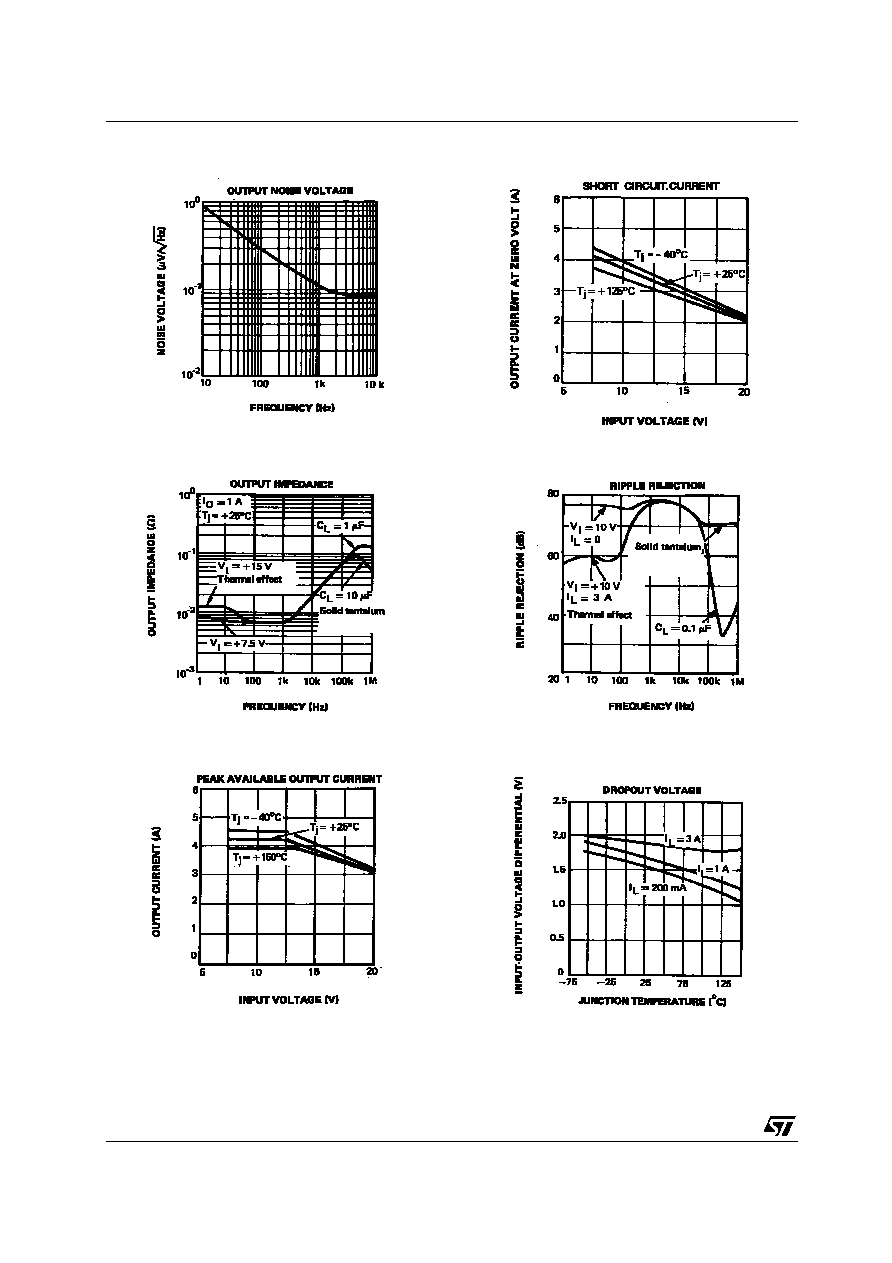
Figure 1 : Output Noise Voltage
Figure 2 : Output Impedance
Figure 3 : Peak Available Output Current
Figure 4 : Short Circuit Current
Figure 5 : Ripple Rejection
Figure 6 : Dropout Voltage
LM123-LM223-LM323
5/10
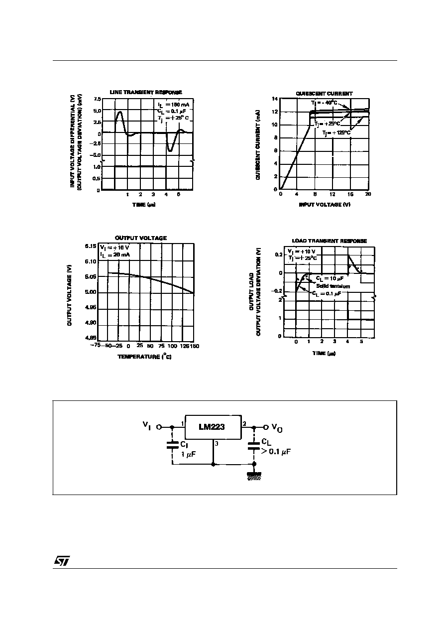
Figure 7 : Line Transient Response
Figure 8 : Output Voltage
Figure 9 : Quiescent Current
Figure 10 : Load Transient Response
TYPICAL APPLICATION
BASIC 3A REGULATOR
C
1
= Required if regulator is distant from filter capacitors.
C
L
= Regulator is stable with no load capacitor into resistive loads.