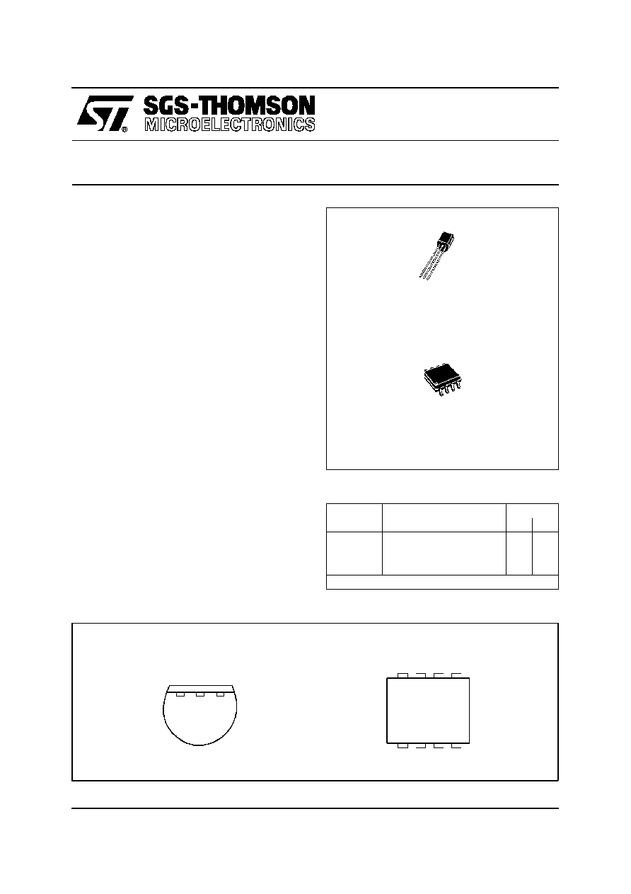
Z
TO92
(Plastic Package)
.
OPERATES from 1V to 40V
.
0.02% V CURRENT REGULATION
.
PROGRAMMABLE from 1
µ
A to 10mA
.
±
3% INITIAL ACCURACY
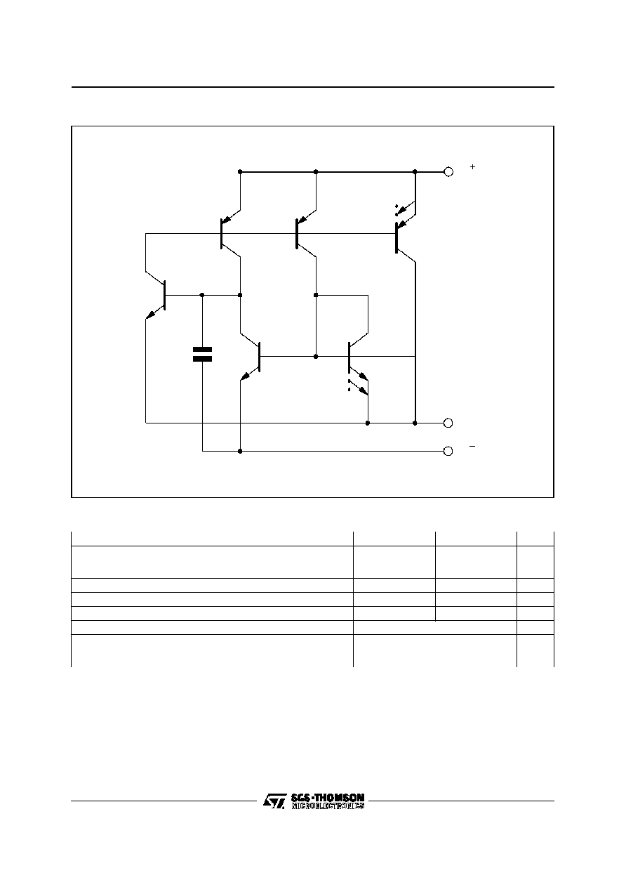
DESCRIPTION
The LM134/LM234/LM334 are 3-terminal adjust-
able current sources characterized by :
- an operating current range of 10000 : 1
- an excellent current regulation
- a wide dynamic voltage range of 1V to 40V
The current is determined by an external resistor
without requiring other external components.
Reverse voltages of up to 20V will only draw a cur-
rent of several microamperes. This enables the
circuit to operate as a rectifier and as a source of cur-
rent in a.c. applications.
For the LM134/LM234/LM334, the voltage on the
control pin is 64mV at +25
o
C and is directly propor-
tional to the absolute temperature (
o
K). The simplest
external resistor connection generates a current
with
0.33%/
o
C temperature dependence. Zero
drift can be obtainedby adding an additionalresistor
and a diode to the external circuit.
PIN CONNECTIONS
D
SO8
(Plastic Micropackage)
V +
AD J
V
-
2
1
3
TO92
(Bottom view)
LM134-LM234
LM334
THREE TERMINAL ADJUSTABLE CURRENT SOURCES
8
7
6
5
1
2
3
4
N C
N C
V
N C
-
ADJ
NC
N C
V+
SO8
(Top view)
ORDER CODES
Part Num-
ber
Temperature
Range
Package
Z
D
LM134
≠55
o
C, +125
o
C
∑
∑
LM234
≠25
o
C, +100
o
C
∑
∑
LM334
0
o
C, +70
o
C
∑
∑
Example : LM134Z
October 1997
1/10

ELECTRICAL CHARACTERISTICS
T
j
= +25
o
C with pulse testing so that junction temperature does not change during testing
(unless otherwise specified)
Parameter
LM134 - LM234
LM334
Unit
Min.
Typ.
Max.
Min.
Typ.
Max.
Set Current Error (V
+
= +2.5V) - (note 1)
10
µ
A
I
SET
1mA
1mA
I
SET
5mA
2
µ
A
I
SET
10
µ
A
3
5
8
6
8
12
%
Ratio of Set Current to V
≠
Current
10
µ
A
I
SET
1mA
1mA
I
SET
5mA
2
µ
A
I
SET
10
µ
A
14
18
14
14
23
14
18
14
14
26
Minimum Operating Voltage
2
µ
A
I
SET
100
µ
A
100
µ
A
I
SET
1mA
1mA
I
SET
5mA
0.8
0.9
1
0.8
0.9
1
V
Average change in set current with input voltage
2
µ
A
I
SET
1mA
+1.5V
V
+
+5V
+5V
V
+
+40V
1mA
I
SET
5mA
+1.5V
V
+
+
+5V
+5V
V
+
+40V
0.02
0.01
0.03
0.02
0.05
0.03
0.02
0.01
0.03
0.02
0.1
0.05
% / V
Temperature Dependence of set current - (note 2)
25
µ
A
I
SET
1mA
0.96 T
T
1.04 T
0.96 T
T
1.04 T
Effective Shunt Capacitance
15
15
pF
Notes :
1. Set current is the current flowing into theV
+
pin. It is determined by the following formula Iset = 67.7mV/R
se t
(T
j
= +25
o
C).
Set current error is expressed as a percent deviation from this amount.
2. I
se t
is directly proportional to absolute temperature (
o
K). I
set
at any temperature can be calculated from
I
se t
= I
O
(T/T
O
) where I
O
is Iset measured at T
O
(
o
K).
LM134-LM234-LM334
3/10
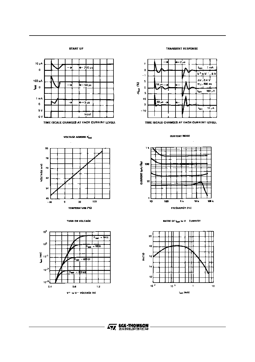
APPLICATION HINT
SLEW RATE
At slew rates above a threshold (see curve) the
LM134, LM234, LM334 can have a non-linear cur-
rent characteristic. The slew rate at which this takes
place is directly proportional to I
set
. At I
set
= 10
µ
A,
dv/dt max. = 0.01V/
µ
S ; at I
set
= 1mA, dv/dt max. =
1V/
µ
S. Slew rates of more than 1V/
µ
S do not dam-
age the circuit nor do they produce high currents.
THERMAL EFFECTS
Internal heating can have a significant effect on cur-
rent regulation for an I
set
above 100
µ
A. For exam-
ple, each increase of 1V in the voltage across the
LM134 at I
set
= 1mA will increase the junction tem-
perature by
0.4
o
C (in still air). The output current
(I
set
) has a temperature coefficient of about
0.33%/
o
C. Thus the change in current due to the in-
crease in temperature will be (0.4) (0.33) = 0.132%.
This is a degradation of 10 : 1 in regulation versus
the true electrical effects. Thermal effects should be
taken into account when d.c. regulation is critical
and I
set
is higher than 100
µ
A. The dissipation of the
connectionsof CB-97 packagecan reduce this ther-
mal effect by a coefficient of more than 3.
SHUNT CAPACITANCE
In certain applications, the 15pF value for the shunt
capacitance should be reduced :
- because of loading problems,
- because of limitation of the output impedance of
the current source in a.c. applications. This reduc-
tion of the capacitance can be easily carried out by
adding a FET as indicatedin the typical applications.
The value of this capacitance can be reduced by at
least 3pF and regulation can be improved by an or-
der of magnitude without any modificationof the d.c.
characteristics (except for the minimum input volt-
age).
NOISE
The current noise produced by LM134, LM234,
LM334 is about 4 times that of a transistor. If the
LM134, LM234, LM334 is utilized as an active load
for a transistor amplifier, the noise at the input will
increase by about 12dB. In most cases this is ac-
ceptable, and a single amplifier can be built with a
voltage gain higher than 2000.
LEAD RESISTANCE
The sense voltage which determines the current of
the LM134, LM234, LM334, is less than 100mV. At
this level, the effects of the thermocouple and the
connection resistance should be reduced by locat-
ing the current setting resistor close to the device.
Do not use sockets for the ICs. A contact resistance
of 0.7
is sufficient to decrease the output current
by 1% at the 1mA level.
SENSING TEMPERATURE
The LM134, LM234, LM334 are excellent remote
controlled temperature sensors because their op-
eration as sources of current preserves their accu-
racy even in the case of long connecting wires. The
output current is directly proportional to the absolute
temperature in degrees Kelvin according to the fol-
lowing equation.
I
set
= (
227
µ
V/
o
K
) (
T
)
R
set
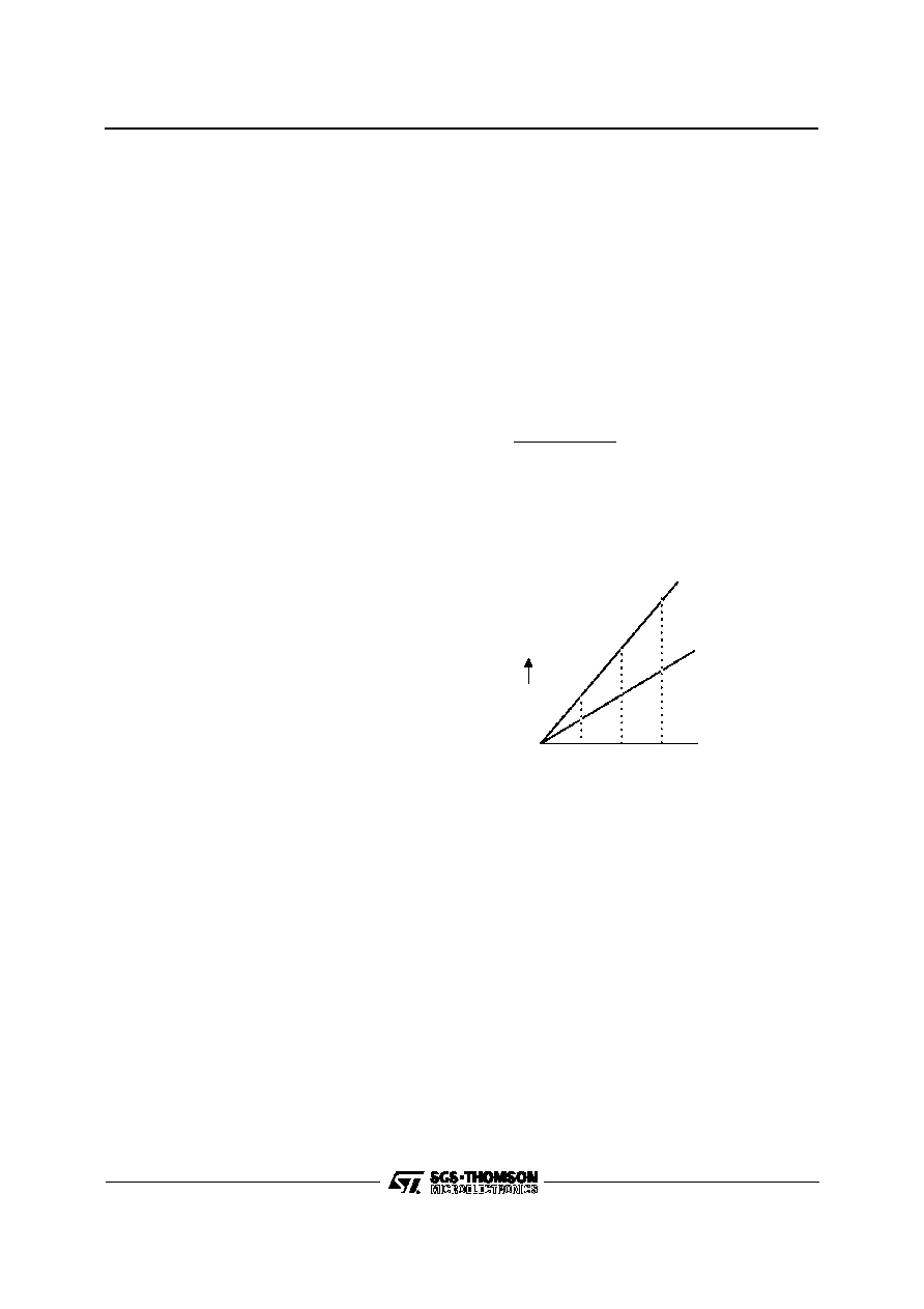
The calibration of the LM134, LM234, LM334 is sim-
plified by the fact that most of the initial accuracy is
due to gain limitation (slope error) and not an offset.
Gain adjustment is a one point trim because the out-
put of the device extrapolates to zero at 0
o
K.
This particularity of the LM134, LM234, LM334 is il-
lustrated in the above diagram. Line abc represents
the sensor current before adjustment and line a'b'c'
represents the desired output. An adjustment of the
gain provided at T2 will move the output from b to
b' and will correct the slope at the same time so that
the output at T1 and T3 will be correct. This gain ad-
justment can be carried out by means of R
set
or the
load resistor utilized in the circuit. After adjustment,
the slope error should be less than 1%. A low tem-
peraturecoefficient for R
set
is necessary to keep this
accuracy. A 33ppm/
o
C temperature drift of R
set
will
give an error of 1% on the slope because the resis-
tance follows the same temperature variations as
the LM134, LM234, LM334. Three wires are re-
quired to isolate R
set
from the LM134, LM234,
LM334. Since this solution is not recommended.
Metal-film resistors with a drift less than 20ppm/
o
C
are now available. Wirewound resistors can be util-
ized when very high stability is required.
T1
T2
T3
0
∞
K
I
set
Desired output
Initial output
c
b
a
a'
b'
c'
LM134-LM234-LM334
5/10