1/46
PRELIMINARY DATA
November 2001
This is preliminary information on a new product now in development or undergoing evaluation. Details are subject to change without notice.
M36DR432C
M36DR432D
32 Mbit (2Mb x16, Dual Bank, Page) Flash Memory
and 4 Mbit (256K x16) SRAM, Multiple Memory Product
FEATURES SUMMARY
s
SUPPLY VOLTAGE
≠ V
DDF
= V
DDS
=1.9V to 2.1V
≠ V
PPF
= 12V for Fast Program (optional)
s
ACCESS TIME: 85,100ns
s
LOW POWER CONSUMPTION
s
ELECTRONIC SIGNATURE
≠ Manufacturer Code: 20h
≠ Top Device Code, M36DR432C: 00A4h
≠ Bottom Device Code, M36DR432D: 00A5h
FLASH MEMORY
s
32 Mbit (2Mb x16) BOOT BLOCK
≠ Parameter Blocks (Top or Bottom Location)
s
PROGRAMMING TIME
≠ 10µs typical
≠ Double Word Programming Option
s
ASYNCRONOUS PAGE MODE READ
≠ Page width: 4 Word
≠ Page Mode Access Time: 35ns
s
DUAL BANK OPERATION
≠ Read within one Bank while Program or
Erase within the other
≠ No Delay between Read and Write
Operations
s
BLOCK PROTECTION ON ALL BLOCKS
≠ WPF for Block Locking
s
COMMON FLASH INTERFACE
≠ 64 bit Security Code
SRAM
s
4 Mbit (256K x 16 bit)
s
LOW V
DDS
DATA RETENTION: 1V
s
POWER DOWN FEATURES USING TWO
CHIP ENABLE INPUTS
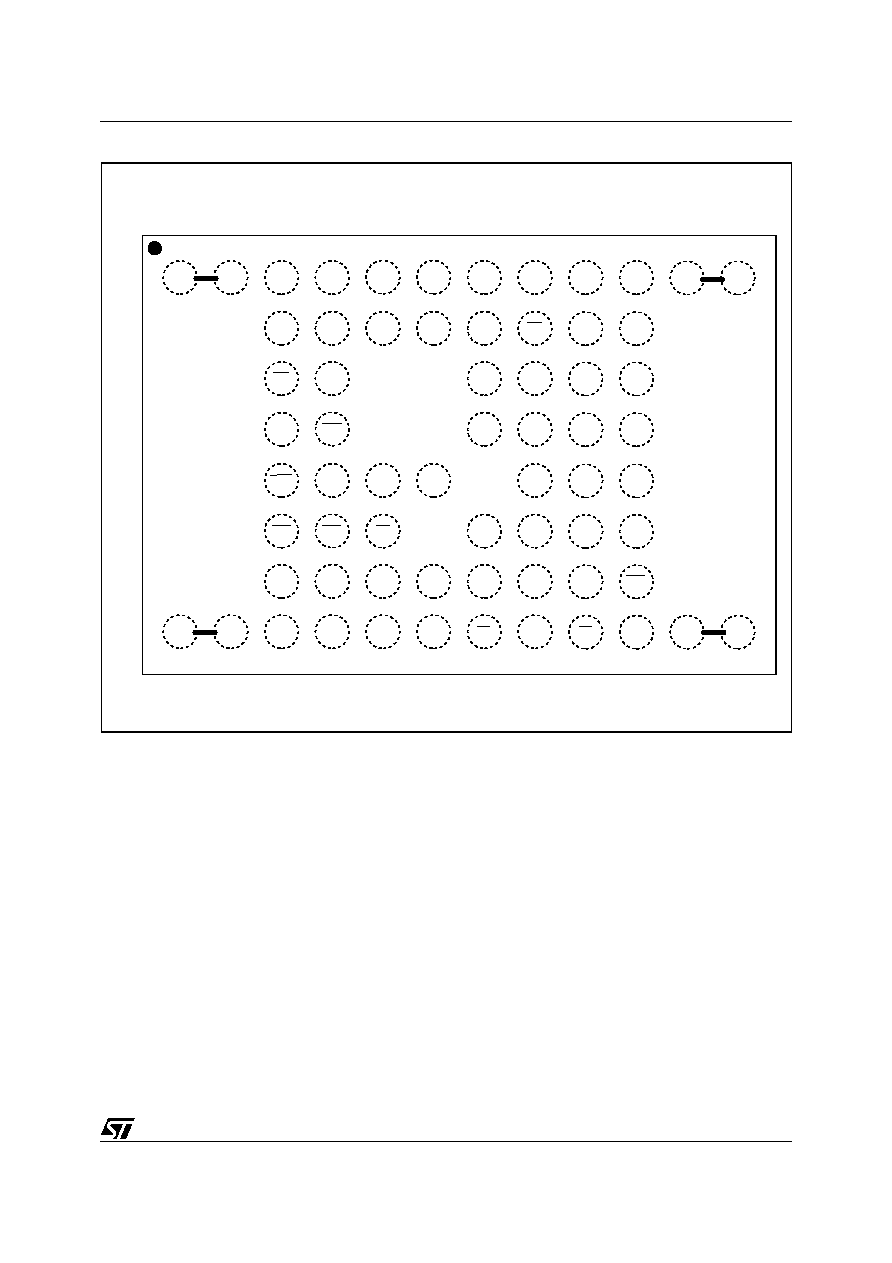
Figure 1. Packages
FBGA
Stacked LFBGA66 (ZA)
8 x 8 ball array

M36DR432C, M36DR432D
4/46
Table 2. Absolute Maximum Ratings
(1)
Note: 1. Except for the rating "Operating Temperature Range", stresses above those listed in the Table "Absolute Maximum Ratings" may
cause permanent damage to the device. These are stress ratings only and operation of the device at these or any other conditions
above those indicated in the Operating sections of this specification is not implied. Exposure to Absolute Maximum Rating condi-
tions for extended periods may affect device reliability. Refer also to the STMicroelectronics SURE Program and other relevant qual-
ity documents.
2. Minimum voltage may undershoot to ≠2V during transition and for less than 20ns.
3. Depends on range.
4. V
DD
= V
DDS
= V
DDF
.
Figure 4. Functional Block Diagram
Symbol
Parameter
Value
Unit
T
A
Ambient Operating Temperature
(3)
≠40 to 85
∞C
T
BIAS
Temperature Under Bias
≠40 to 125
∞C
T
STG
Storage Temperature
≠55 to 150
∞C
V
IO
(2)
Input or Output Voltage
≠0.2 to V
DD
(4)
+ 0.3
V
V
DDF
Flash Chip Supply Voltage
≠0.5 to 2.7
V
V
DDS
SRAM Chip Supply Voltage
≠0.2 to 2.6
V
V
PPF
Program Voltage
≠0.5 to 13.0
V
AI90205
Flash Memory
32 Mbit (x16)
VSSF
EF
GF
WF
RPF
WPF
E1S
E2S
GS
WS
UBS
LBS
DQ0-DQ15
VDDF
VPPF
A18-A20
A0-A17
SRAM
4 Mbit (x16)
VSSS
VDDS

5/46
M36DR432C, M36DR432D
SIGNAL DESCRIPTIONS
See Figure 2 and Table 1.
Address Inputs (A0-A17). Addresses A0 to A17
are common inputs for the Flash chip and the
SRAM chip. The address inputs for the Flash
memory are latched during a write operation on
the falling edge of the Flash Chip Enable (EF) or
Write Enable (WF), while address inputs for the
SRAM array are latched during a write operation
on the falling edge of the SRAM Chip Enable lines
(E1S or E2S) or Write Enable (WS).
Address Inputs (A18-A20). Address A18 to A20
are address inputs for the Flash chip. They are
latched during a write operation on the falling edge
of Flash Chip Enable (EF) or Write Enable (WF).
Data Input/Outputs (DQ0-DQ15). The input is
data to be programmed in the Flash or SRAM
memory array or a command to be written to the
C.I. of the Flash chip. Both are latched on the ris-
ing edge of Flash Chip Enable (EF) or Write En-
able (WF) and, SRAM Chip Enable lines (E1S or
E2S) or Write Enable (WS). The output is data
from the Flash memory or SRAM array, the Elec-
tronic Signature Manufacturer or Device codes or
the Status register Data Polling bit DQ7, the Tog-
gle Bits DQ6 and DQ2, the Error bit DQ5 or the
Erase Timer bit DQ3. Outputs are valid when
Flash Chip Enable (EF) and Output Enable (GF) or
SRAM Chip Enable lines (E1S or E2S) and Output
Enable (GS) are active. The output is high imped-
ance when the both the Flash chip and the SRAM
chip are deselected or the outputs are disabled
and when Reset (RPF) is at a V
IL
.
Flash Chip Enable (EF). The Chip Enable input
for Flash activates the memory control logic, input
buffers, decoders and sense amplifiers. EF at V
IH
deselects the memory and reduces the power con-
sumption to the standby level and output do Hi-Z.
EF can also be used to control writing to the com-
mand register and to the Flash memory array,
while WF remains at V
IL
. It is not allowed to set EF
at V
IL
, E1S at V
IL
and E2S at V
IH
at the same time.
Flash Write Enable (WF). The Write Enable in-
put controls writing to the Command Register of
the Flash chip and Address/Data latches. Data are
latched on the rising edge of WF.
Flash Output Enable (GF). The Output Enable
gates the outputs through the data buffers during
a read operation of the Flash chip. When GF and
WF are High the outputs are High impedance.
Flash Reset/Power Down Input (RPF). The RPF
input provides hardware reset of the memory
(without affecting the Configuration Register sta-
tus), and/or Power Down functions, depending on
the Configuration Register status. Reset/Power
Down of the memory is achieved by pulling RPF to
V
IL
for at least t
PLPH
. When the reset pulse is giv-
en, if the memory is in Read, Erase Suspend Read
or Standby, it will output new valid data in t
PHQ7V1
after the rising edge of RPF. If the memory is in
Erase or Program modes, the operation will be
aborted and the reset recovery will take a maxi-
mum of t
PLQ7V
. The memory will recover from
Power Down (when enabled) in t
PHQ7V2
after the
rising edge of RPF. See Tables 1, 26 and Figure
11.
Flash Write Protect (WPF). Write Protect is an
input to protect or unprotect the two lockable pa-
rameter blocks of the Flash memory. When WPF
is at V
IL
, the lockable blocks are protected. Pro-
gram or erase operations are not achievable.
When WPF is at V
IH
, the lockable blocks are un-
protected and they can be programmed or erased
(refer to Table 17).
SRAM Chip Enable (E1S, E2S). The Chip En-
able inputs for SRAM activate the memory control
logic, input buffers and decoders. E1S at V
IH
or
E2S at V
IL
deselects the memory and reduces the
power consumption to the standby level. E1S and
E2S can also be used to control writing to the
SRAM memory array, while WS remains at V
IL
. It
is not allowed to set EF at V
IL
, E1S at V
IL
and E2S
at V
IH
at the same time.
SRAM Write Enable (WS). The Write Enable in-
put controls writing to the SRAM memory array.
WS is active low.
SRAM Output Enable (GS). The Output Enable
gates the outputs through the data buffers during
a read operation of the SRAM chip. GS is active
low.
SRAM Upper Byte Enable (UBS). Enable
the
upper bytes for SRAM (DQ8-DQ15). UBS is active
low.
SRAM Lower Byte Enable (LBS). Enable
the
lower bytes for SRAM (DQ0-DQ7). LBS is active
low.
V
DDF
Supply Voltage (1.9V to 2.1V). Flash memory
power supply for all operations (Read, Program and
Erase).
V
PPF
Programming Voltage (11.4V to 12.6V).
Used to provide high voltage for fast factory pro-
gramming. High voltage on V
PPF
pin is required to
use the Double Word Program instruction. It is
also possible to perform word program or erase in-
structions with V
PPF
pin grounded.
V
DDS
Supply Voltage (1.9V to 2.1V). SRAM pow-
er supply for all operations (Read, Program).
V
SSF
and V
SSS
Ground. V
SSF
and V
SSS
are the
reference for all voltage measurements respec-
tively in the Flash and SRAM chips.