 | ÐлекÑÑоннÑй компоненÑ: ST20184 | СкаÑаÑÑ:  PDF PDF  ZIP ZIP |
Äîêóìåíòàöèÿ è îïèñàíèÿ www.docs.chipfind.ru
1/7
ST20190
June 2004
This is preliminary information on a new product now in development. Details are subject to change without notice.
1
APPLICATIONS
Low end and high end ADSL Bridge and Router
solutions
ADSL Modems / routers for residential and
SOHO broadband access to www and
corporate VPNs
Integrated Access Devices offering VoDSL or
VoIP applications
Home gateway solutions
2
FEATURES
High Integration
2 chips, Line to ATM
Direct ATM Interface
Line Driver integrated
Highly reduced bill of material cost
Support for multiple ADSL standards:
ANSI T1.413 Issue2
ITU G.992.1 (G.dmt)
Annex A, Annex B, Annex C
ITU G.992.2 (G.Lite)
ITU G.992.3 (ADSL2)
Annex A, B, C, I, J and L
ITU G.992.4 (G.Lite bis)
ITU G.992.5 (ADSL2+)
Annex A, B, C, I, J and L
Support of ReachDSLTM with digital com-
panion chip
Cat II functionality: Trellis coding and echo
cancellation
Dual latency support: fast + interleaved
Small footprint packages allow high density
board designs
Embedded controller with cache for powerful
and flexible on chip control of the modem
operation
Complete modem package
No dependency on external processor and
easy,straight forward integration with external
network processors
Full reference design kit for modem manufac-
turers, including schematics, layout, BoM,
HW design guide, firmware
Highest Performance
Fully rate-adaptive
ADSL mode > 12 Mbps in Downstream and >
1 Mbps in Upstream
ADSL+ mode > 20 Mbps in Downstream and
> 2 Mbps in Upstream when using 64 tones
(annex L)
3
OVERALL DESCRIPTION
The ST20190 is a new generation ADSL chipset
from STMicroelectronics. It is highly integrated
and has the flexibility to offer all standards, all an-
nexes while being fully optimised for CPE applica-
tions. It provides all the required functions to
implement a complete Utopia rate adaptive DMT
ADSL modem. It consists of the optimised ADSL
Analogue Front-End chip ST20184 and the digital
chip ST20196 which includes a DMT/ATM mo-
dem, and a dedicated ADSL Transceiver Control-
ler with associated Firmware.
As shown in Fig.2, the chipset interfaces have
been defined to allow direct integration into sys-
tems design, reducing both time-to-market and im-
DATA BRIEF
ADSL, ADSL2 and ADSL+
Modem Chipset for CPE Applications with Utopia II Interface
REV. 1
Figure 1. Package
Table 1. Order Codes
Part Number
Package
ST20184
TQFP100
ST20196
LBGA208
TQFP100
LBGA208
ST20190
2/7
plementation risks. The data interface is implemented as an ATM Utopia interface. A HW/FW command
and control interface (CtrlE) to communicate with external management entities, is directly provided, with-
out need for glue logic.
The chipset employs Discrete Multi-Tone modulation as specified in ANSI T1.413. It also supports ETSI
TS 101 388 and ITU standards G.992.1 (G.dmt) including Annex A, B and C; G.992.2 (G.lite) annex A, B
and C; G.992.3 (ADSL2) including Annex A, B, C, I, J and L; G.992.5 (G.ADSL+) including Annex A, B, C,
I, J and Annex L.
Flexible bit assignment is foreseen to support ADSL overlay over POTS and ISDN but also All Digital loop
and overlapping spectra. Additional Reed-Solomon forward error correction with optional interleaving pro-
vides maximum noise immunity.
4
THE MODEM ENVIRONMENT
An integrated ADSL-compatible line driver is used to drive the telephone twisted pair, and a POTS/ISDN
splitter or adequate distributed filtering is required to split the baseband analogue telephone or ISDN sig-
nal from the modulated ADSL signal. In G.Lite mode, the splitter can be removed and replaced by distrib-
uted POTS filters. Brief characteristics of the system are given in Section 6. The bit rate can be varied in
steps of 32 kbits/s in ADSL and in steps of 1 kbit/s in ADSL2/ADSL+ mode.
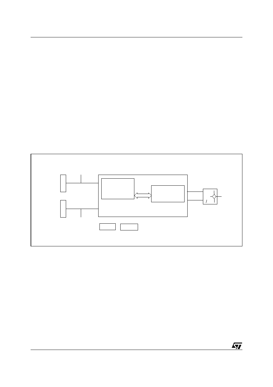
Figure 2. Utopia Chipset Block Diagram
5
CHIPSET FUNCTIONS
The functions performed by each IC are as follows:
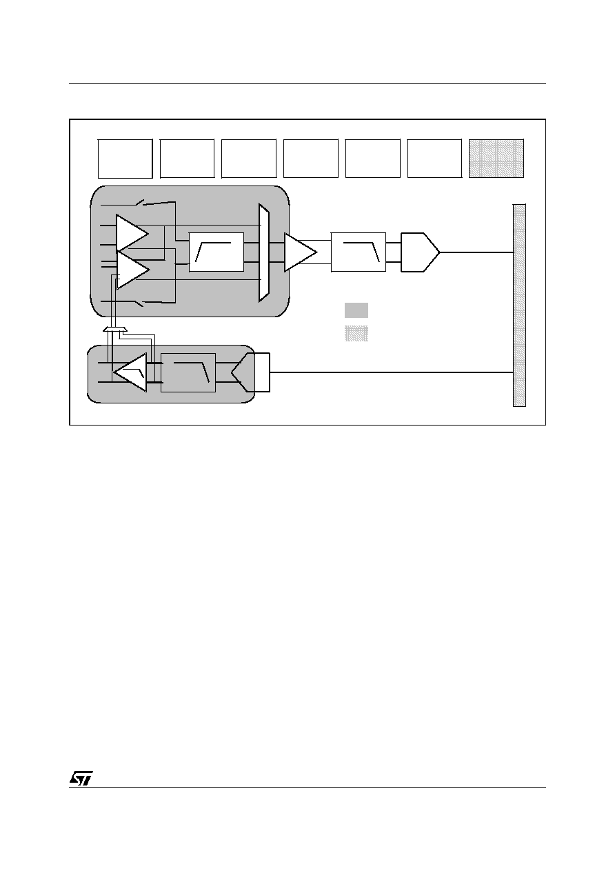
5.1 ST20184
This CMOS IC contains the analogue functions required in the transceiver. In order to cope with the high
attenuation of the line and in order to maintain an acceptable noise level of the signal, Programmable gain
amplifiers have been implemented at the analogue front of the transmission and reception paths. In Re-
ception, the signal goes through a LNA, a high pass filter to eliminate echo and LNA before a low pass
filter for anti-aliasing. The AD and DA converters provide 14-bit resolution at 2.2 MHz sampling rate.
Finally, for the transmission part, the control of the external hybrid driver is done by a highly integrated
linear line driver.
Line
- DMT Modem
- ATM framer
- Microcontroller
ST20196
ST20184
Analog
Front End
~
~
Utopia I or II
Management
Entity
ATM
SDRAM
flash
EPROM
(Optional)
Control
CtrlE
3/7
ST20190
Figure 3. Block Diagram of ST20184
5.2 ST20196
5.2.1 Discrete Multi Tone (DMT) Modulation and Demodulation
The ST20196 includes a digital Quadrature Amplitude Modulation (QAM) mapper/demapper which allows
coding of up to 15 bits per tone. The device incorporates the necessary Inverse- and Fast Fourier Trans-
form (IFFT, FFT), an innovative unique Per Tone Equalizer (PTEQ), echo cancelling (EC), Trellis coding
and decoding plus timing units and a fully digital clock recovery scheme (TDI). These last blocks feature
efficient synchronization algorithms to improve the efficiency of the recovery of data. The ST20196 per-
formances rely on embedded programmable cores.
In ADSL2 mode the modem supports diagnostics modes, enhanced power management modes to reduce
the CO power (L2), 1 bit constellation, relocatable and modulated pilot.
5.2.2 Framing Functions
The ST20196 incorporates framing functions for the generic and ATM Transmission Convergence (TC)
layers. The new TC layer architecture is fully under the control of an embedded controller. This provides
the flexibility to adapt to different framing variants via firmware. The TC consists of data scrambling and
Reed-Solomon error correction with and without inter-leaving. It also includes the rate converter function-
ality as defined in G.dmt Annex C. Several framing variants are implemented (such as interleaved and
non-interleaved modes, full and reduced overhead) to ensure compliance with ANSI T1.413 Issue 2 and
ITU G.992.1 (G.dmt), G.992.2 (G.Lite), G.992.3 and G.992.4.
RX LPF
ADC
TX LPF
DAC
D
I
G
I
T
A
L
TXLD
TXP
TXN
Dying Gasp
Tuning Circuit
I/V Reference
VCXO
(optional)
CTRL/TST
Interface
2.5V Regulator
+
POR
LNA1ab
RX HPF
LNA2
RXP1
RXN1
LNA1c
RXP2
RXN2
RXP3
RXN3
Bypass
Bypass
Loopback
5V area
Digital
Hybrid
switches
ST20190
4/7
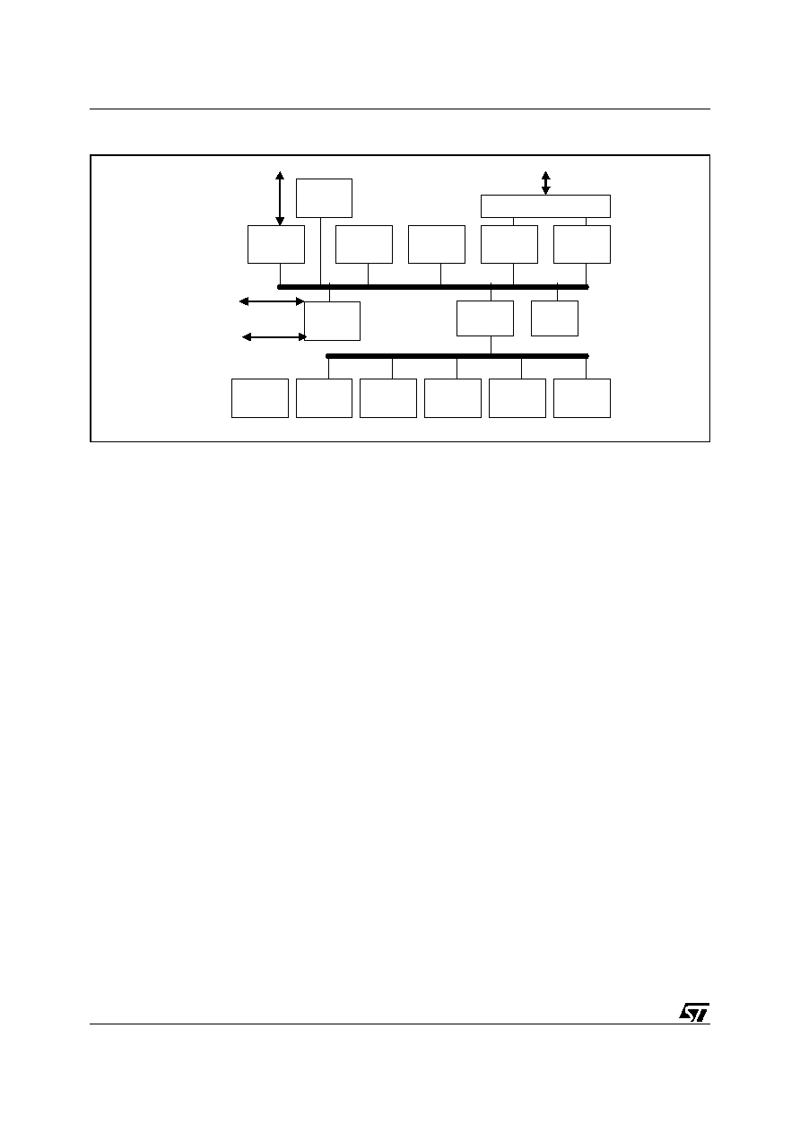
Figure 4. Block Diagram of ST20196
5.2.3 Interface to Utopia Bus
The IC contains the ATM-related functions to interface with the ATM utopia bus an supports level 1 and 2
modes.
5.2.4 Control of Transceiver Chip
The ST20196 runs the firmware controlling the operations of the ADSL transceiver (AFE, DMT modem,
Framer). During modem initialisation, the controller computes and sets up parameters for all programma-
ble DMT functions, filters and equalizers. The ATM TC includes cell level functions (such as cell delinea-
tion, insertion/ extraction of idle cells, payload scrambling, HEC check) and data frame generation. The
controller is able to run in different rate-adaptive modes as defined by the operator. During operation, the
ST20196 performs continuous line monitoring and initiates consecutive actions as specified by the oper-
ator (e.g. bit-swapping, dynamic bit-rate adaptation, power management, ... etc.) and collects perfor-
mance and error information for use by management entities.
5.2.5 Interface to Management Entities
The ST20196 also runs the communication protocol to interface with external management entities. A spe-
cific ADSL modem control interface has been defined to ease the integration with both systems hardware
and firmware. This control communication channel is used to transfer information and commands between
modem and management entities. These commands/responses are fully described in the CtrlE specifica-
tion and can be categorized as follows:
- Configuration of a modem line
- De-allocation of a modem line
- Operational Data Retrieval
- Performance Data Retrieval
- Defect Retrieval
FLASH
CTRL
SDRAM
CTRL
EBI
ROM
RAM
CTRLE
ARM946
AHB2APB
INTERRUPT
CTR
RT
TIMERS
WATCHDOG
UART
GPIO
JTAG
DMT
CORE
TIC
AFE
Interface
ATM
Interface

5/7
ST20190
6
SUMMARY OF CHARACTERISTICS ST20190
6.1 ST20184 FEATURES
Fully integrated ADSL line driver concept (minimises external components)
Standards support for:
ANSI T1.413 Issue 2
ITU G.992.1 (G.dmt)
Annex A, B and C
ITU G.992.2 (G.lite)
ITU G.992.3 (ADSL2)
Annex A, B, C, I, J and L
ITU G.992.5 (ADSL2+)
Annex A, B, C, I, J and L
Support of ReachDSL with digital companion chip
14 bit
ADC with equivalent ENOB @ 2.2 MS/s
8.8MS/s DAC (14bits)
Integrated ADSL highpass filter for POTS and Echo cancellation
Fixed XTAL
2.2MHz signal bandwidth / 4.3 kHz tone spacing
Supply voltages: 3.3V and 5V
Temperature range: -40°C to 85°C
Typical power consumption 900 mW
Package: TQFP100
6.2 ST20196 FEATURES
DMT modulation
Max. number of bit per tone: 15 bits (32766 constellation points)
Max. number of tones: 512 tones
Flexible bit assignment
Max clock speed: 36 MHz
Max. tone spacing: 4.325 kHz
RS encoder: max code word 256 bytes
ATM Processor:
ATM cell buffering
Cell counting
Insert/Extract, Idle/Unassigned ATM cells (rate adaptation)
ATM HEC generation module (CCITT I.432)
ATM payload scrambler: payload width: 48 bytes
Full support of Utopia level 1 or 2 interface
Cached ARM controller for improved performance
Modem Command interface
compatible with Utopia level 2 8-bit parallel management interface
ST's CtrlE modem control command protocol
Access through parallel 8bit bus or asynchronous serial port
Dual port RAM mailbox
Interface to ReachDSLTM engine
Supply voltages: 3.3V and 1.2V
Temperature range: -40°C to 85°C
Typical power consumption 700 mW
Package: LBGA208
Document Outline