Æ
1/10
DESCRIPTION
The ST20-JPI parallel port to JTAG interface is
a host interface to allow connection from a PC
parallel port to any JTAG diagnostic controller
based ST20 development board. The interface
plugs into any standard PC 25 way D-type
parallel port. Supported parallel port modes
are:
∑
Nibble mode
∑
Byte mode
∑
EPP mode
depending on which mode the host PC can
support. Connection to the development target
is via a 20 way IDC JTAG connector. Once
connected, the development target can be
accessed using the MS Windows drivers
supplied with the standard ST20 toolset.
FEATURES
∑
Desktop mounted parallel port to JTAG inter-
face
∑
Standard 25 way D-type parallel port connec-
tion
∑
Standard 26 way D-type differential OS-Link
port for connection to a B300.
∑
Standard 20 way IDC cable for JTAG connec-
tion.
∑
Plug top power supply
∑
Supports nibble, byte and EPP mode parallel
port standards
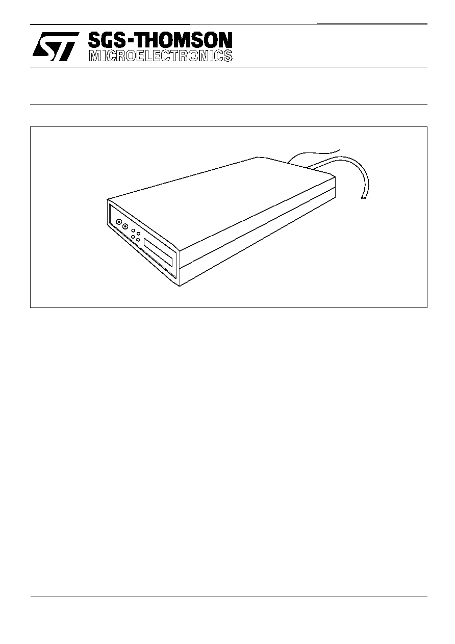
PRODUCT INFORMATION
PC PARALLEL PORT TO JTAG INTERFACE
ST20-JPI
42 1685 00
September 1996

Contents
2/10
Æ
Æ
1
Introduction . . . . . . . . . . . . . . . . . . . . . . . . . . . . . . . . . . . . . . . . . . . . . . . . . . . . . . . . . . . . . 3
2
Installation . . . . . . . . . . . . . . . . . . . . . . . . . . . . . . . . . . . . . . . . . . . . . . . . . . . . . . . . . . . . . . 4
2.1
Hardware Installation - PC ..................................................................................................................... 4
2.2
Hardware Installation - B300 ................................................................................................................. 5
2.3
Software Installation .............................................................................................................................. 5
3
Connectors . . . . . . . . . . . . . . . . . . . . . . . . . . . . . . . . . . . . . . . . . . . . . . . . . . . . . . . . . . . . . 6
3.1
The ST20-JPI front panel ....................................................................................................................... 6
3.2
The ST20-JPI rear panel ....................................................................................................................... 6
3.3
Differential Link Connection ................................................................................................................... 7
3.4
JTAG Connection .................................................................................................................................. 7
3.5
TrigIn/TrigOut SMB Coaxial Connectors ............................................................................................... 8
3.6
Power Supply Connector ....................................................................................................................... 8
4
Recommended Target Circuitry . . . . . . . . . . . . . . . . . . . . . . . . . . . . . . . . . . . . . . . . . . . . 8
5
Field Support . . . . . . . . . . . . . . . . . . . . . . . . . . . . . . . . . . . . . . . . . . . . . . . . . . . . . . . . . . . . 9
6
Ordering information . . . . . . . . . . . . . . . . . . . . . . . . . . . . . . . . . . . . . . . . . . . . . . . . . . . . . 9

ST20-JPI
3/10
Æ
1
Introduction
The ST20-JPI parallel port to JTAG interface is a host interface to allow connection from a PC
parallel port to any JTAG based ST20 development board. The interface plugs into any standard
PC 25 way D-type parallel port. Supported parallel port modes are:
∑
Nibble mode
∑
Byte mode
∑
EPP mode
depending on which mode the host PC can support. Connection to the development target is via a
JTAG connector.
Once connected, the development target can be accessed using the MS Windows
drivers supplied with the standard ST20 toolset.
ST20-JPI
4/10
Æ
2
Installation
2.1
Hardware Installation - PC
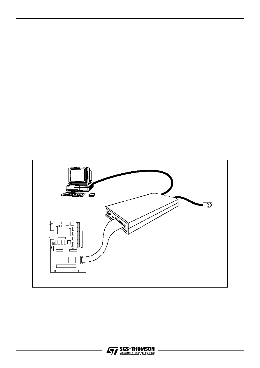
The ST20-JPI has six connections: Parallel port; Differential OS-Link, JTAG, TrigIn, TrigOut and
Power supply. To install the hardware connecting to a PC, the following steps should be followed:
∑
Plug the 25-way D-type of the parallel port cable built into the interface, into the parallel port
of the PC.
∑
Plug the target development system into the 20-way IDC connector using a 20 way IDC
cable.
∑
Plug power supply cable into PSU socket of the interface.
∑
Plug the power supply into the mains socket.
∑
Switch on the PC.
∑
Switch on the power supply. The LEDs on the interface should illuminate once the software
is running. For a description of the meaning of the LEDs, see the ST20 toolset documenta-
tion.
Figure 2.1 ST20-JPI connections basic configuration
Mains PSU
Target development board
ST20-JPI
Parallel port to JTAG interface
Host
ST20

ST20-JPI
5/10
Æ
2.2
Hardware Installation - B300
The ST20-JPI can also be attached to the Ethernet via a B300. To install the hardware connecting
to a B300, the following steps should be followed:
∑
Connect the B300 to the ST20-JPI using a Differential OS-Link cable supplied with the
B300.
∑
Plug the target development system into the 20-way IDC connector using a 20 way IDC
cable.
∑
Plug power supply cable into PSU socket of the interface.
∑
Plug the power supply into the mains socket.
∑
Switch on the B300.
∑
Switch on the power supply to the ST20-JPI. The LEDs on the interface should illuminate
once the software is running. For a description of the meaning of the LEDs, see the ST20
toolset documentation.
∑
Switch on the Target power supply.
2.3
Software Installation
For installation of the DLL and VxD drivers, please refer to the ST20 Toolset software installation
documentation.