ST5088
PROGRAMMABLE AUDIO FRONT END
FOR DIGITAL PHONES AND ISDN TERMINALS
FEATURES:
Complete CODEC and FILTER system including:
PCM ANALOG TO DIGITAL AND DIGITAL TO
ANALOG CONVERTERS
POWERFUL ANALOG FRONT END CAPA-
BLE TO INTERFACE DIRECTLY:
- Microphone Dynamic or Electrete
- Earpiece down to 100
or up to 150nF
- Loudspeaker down to 50
or Buzzer up to
600nF.
TRANSMIT BAND-PASS FILTER
ACTIVE RC NOISE FILTER
RECEIVE LOW-PASS FILTER WITH SIN X/X
CORRECTION
MU-LAW OR A-LAW SELECTABLE COM-
PANDING CODER AND DECODER
PRECISION VOLTAGE REFERENCE
Phones Features:
DUAL SWITCHABLE MICROPHONE AMPLI-
FIER INPUTS. GAIN PROGRAMMABLE: 15
dB RANGE, 1 dB STEP.
LOUDSPEAKER AMPLIFIER OUTPUT.
SWITCHABLE MAXIMUM GAIN: +9dB/+27dB
WITH AUTOMATIC DIGITAL ANTICLIPPING
SYSTEM. aTTENUATION PROGRAMMABLE:
30dB RANGE, 2dB STEP.
SEPARATE EARPIECE AMPLIFIER OUTPUT.
ATTENUATION PROGRAMMABLE: 15 dB
RANGE, 1 dB STEP.
AUXILIARY TAPE RECORDER ANALOG IN-
TERFACE: Tx + Rx COMBINED OUTPUT.
AUXILIARY SWITCHABLE EXTERNAL RING
INPUT (EAIN).
TRANSIENT SUPRESSION SIGNAL DURING
POWER ON.
INTERNAL
PROGRAMMABLE
SIDETONE
CIRCUIT. ATTENUATION PROGRAMMABLE:
15 dB RANGE, 1 dB STEP, INDEPENDENT
FROM Rx CONTROL.
INTERNAL RING OR TONE GENERATOR IN-
CLUDING DTMF TONES, SINEWAVE OR
SQUAREWAVE
WAVEFORMS.
ATTENU-
ATION PROGRAMMABLE: 27 dB RANGE, 3
dB STEP.
RINGER CONTROL PROGRAMMABLE IN-
TERNALLY (
�
P) OR EXTERNALLY (pin AT)
COMPATIBLE WITH HANDS-FREE CIRCUIT
TEA7540.
ON CHIP SWITCHABLE ANTI-ACOUSTIC
FEED-BACK CIRCUIT (ANTI-LARSEN).
General Features:
EXTENDED TEMPERATURE RANGE OP-
ERATION (*) � 25
�
C TO +85
�
C.
EXTENDED POWER SUPPLY RANGE 5V
�
10%.
60 mW OPERATING POWER (TYPICAL).
1.0 mW STANDBY POWER (TYPICAL).
CMOS DIGITAL INTERFACES.
SINGLE + 5V SUPPLY.
DIGITAL LOOPBACK TEST MODE.
PROGRAMMABLE DIGITAL AND CONTROL
INTERFACES:
� Digital PCM Interface associated with
separate
serial
Control
Interface
MI-
CROWIRE
TM
compatible.
� GCI interface compatible.
(*) Functionality guaranteed in the range � 25
�
C to +85
�
C;
Timing and Electrical Specifications are guaranteed in the range
� 5
�
C to +70
�
C.
APPLICATIONS:
ISDN TERMINALS.
DIGITAL TELEPHONES
CT2 AND GSM APPLICATIONS
This is advanced information on a new product now in development or undergoing evaluation. Details are subject to change without notice.
December 1999
�
ORDERING NUMBERS:
ST5088D
ST5088FN
PLCC28
SO28
1/33
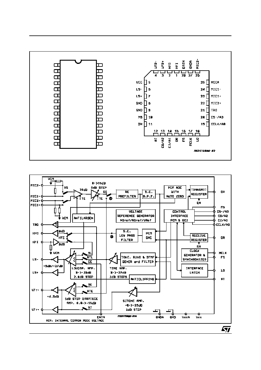
BLOCK DIAGRAM
PIN CONNECTION (Top view)
HFI
HFO
VFR+
VFR-
VCC
LS+
LS-
GND
MS
CS-/A3
MIC 2+
MIC 1+
TRO
MIC 1-
VCCA
MIC 2-
GNDA
EAIN
1
3
2
4
5
6
7
8
9
26
25
24
23
22
20
21
19
27
10
28
DX
CCLK/A0
D93TL047
AT
CO/A2
CI/A1
MCLK
LO
N.C.
11
12
13
18
16
17
15
14
DR
FS
PLCC28
SO28
ST5088
2/33
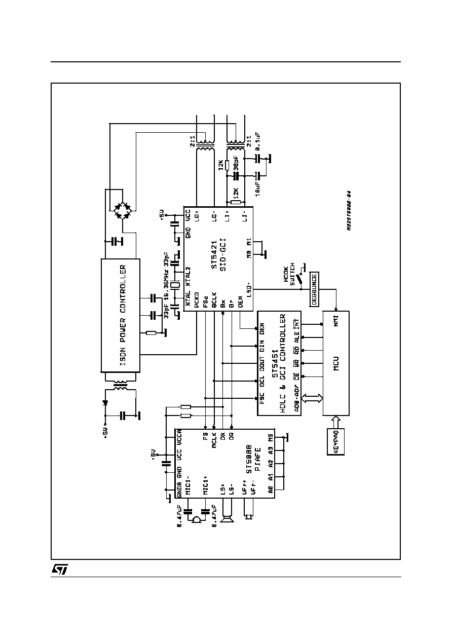
TYPICAL ISDN TELEPHONE SET APPLICATION
ST5088
3/33
GENERAL DESCRIPTION
ST5088 PIAFE is a combined PCM CODEC/FIL-
TER device optimized for ISDN Terminals and Digi-
tal Telephone applications. This device is A-law
and Mu-law selectable and offers a number of pro-
grammable functions accessed through a serial
control channel.
Depending on mode selected, channel control is
provided by means of a separate serial channel
control MICROWIRE compatible or multiplexed
with the PCM voice data channel in a GCI com-
patible format requiring only 4 digital interface
pins. When separate serial control interface is se-
lected, PCM interface is compatible with Combo I
and Combo II families of devices such as
ETC5057/54, TS5070/71.
PIAFE is built using SGS-THOMSON's advanced
HCMOS process.
Transmit section of PIAFE consists of an amplifier
with switchable high impedance inputs followed
by a programmable gain amplifier, an active RC
antialiasing pre-filter to provide attenuation of high
frequency noise, an 8th order switched capacitor
band pass transmit filter and an A-law/Mu-law se-
lectable compandig encoder.
Receive section consist of an A-law/Mu-law se-
lectable expanding decoder which reconstructs
the analog sampled data signal, a 3400 Hz low
pass filter with sin X/X correction followed by two
separate programmable attenuation blocks and
two power amplifiers: one can be used to drive an
earpiece, and the other to drive a 50
loud-
speaker or a piezo transducer up to 600nF.
When the loudspeaker section is set up with
maximum gain (+27dB) the device provide inter-
nally a programmable digital anticlipping system
to avoid output distortion.
Programmable functions on PIAFE include a
Ring/Tone generator which provides one or two
tones and can be directed to earpiece or to loud-
speaker (or buzzer).
A simple ringer control interface can bypass
�
P
control of sweep frequency and ring ON/OFF
phases.
A separate programmable gain amplifier allows
gain control of the signal injected. Ring/Tone gen-
erator provides sinewave or squarewave signal
with precise frequencies which may be also di-
rected to the input of the Transmit amplifier for
DTMF tone generation.
An auxiliary analog input (EAIN) is also provided
to enable for example the output of an external
band limited Ring signal to the Loudspeaker.
Transmit signal may be fed back into the receive
ampifier with a programmable attenuation to pro-
vide a sidetone circuitry.
A switchable anti-accoustic feed-back system
cancels the larsen effect in speech monitoring ap-
plication.
Two additional pins are provided for insertion of
an external Handfree function in the Loudspeaker
receive path.
An output latch controlled by register program-
ming permits external device control.
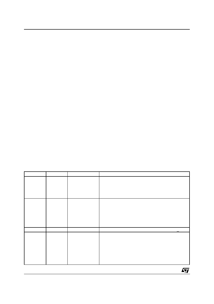
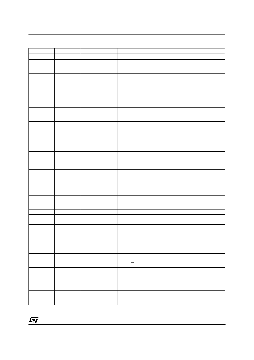
PIN FUNCTIONS
SO
PLCC
Name
Description
1,2
1,2
HFI, HFO
Hands free I/Os:
These two pins can be used to insert an external Handfree circuit
such as the TEA 7540 in the receive path. HFO is an output which
provides the signal issued from output of the receive low pass filter
while HFI is a high impendance input which is connected directly to
one of the inputs of the Loudspeaker amplifier.
3,4
3,4
V
Fr+
, V
Fr�
Receive analog earpiece amplifier complementary
outputs, capable of driving load impedances between 100
and 400
or a piezo ceramic transducer up to 150nF.
These outputs can drive directly earpiece transductor. The
signal at this output can drive be the summ of:
- Receive Speech signal from D
R
,
- Internal Tone Generator,
- Sidetone signal.
5
5
V
CC
Positive power supply input for the digital section. +5 V + 10%.
6,7
6,7
LS-,LS+
Receive analog loudspeaker amplifier complementary outputs,
intended for driving a Loudspeaker: 80 mW on 50
load
impedance can be provided at low distorsion meeting
specifications.
Alternatively this stage can drive a piezo transducer up to
600nF. The signal at these outputs can be the sum of:
- Receive Speech signal from D
R
,
- Internal Tone generator,
- External input signal from EAIN input.
ST5088
4/33
PIN FUNCTIONS (continued)
SO
PLCC
Name
Description
8
8,9
GND
Ground: All digital signals are referenced to this pin.
9
10
MS
Mode Select: This input selects COMBO I/II interface mode
with separate MICROWIRE Control interface when tied high
and GCI mode when tied low.
10
11
D
X
Transmit Data ouput: Data is shifted out on this pin during the
assigned transmit time slots. Elsewhere D
X
output is in the
high impendance state. In COMBO I/II mode, voice data byte
is shifted out from TRISTATE output D
X
at the MCLK
frequency on the rising edge of MCLK. In GCI mode, voice
data byte and control bytes are shifted out from OPEN-DRAIN
output D
X
at half the MCLK. An external pull up resistor is
needed.
11
12
AT
Alternate Tone: Ring frequency out is controlled without
�
P
intervention. Tri-state logic controls: f1 (Vcc), f2 (GND), pause
(High Impedance).
14
15
D
R
Receive data input: Data is shifted in during the assigned
Received time slots. In the COMBO I/II mode, voice data byte
is shifted in at the MCLK frequency on the falling edges of
MCLK. In the GCI mode, PCM data byte and contol byte are
shifted in at half the MCLK frequency on the receive rising
edges of MCLK. There is one period delay between transmit
rising edge and receive rising edge of MCLK.
15
16
FS
Frame Sync input: This signal is a 8kHz clock which defines
the start of the transmit and receive frames. Either of three
formats may be used for this signal: non delayed timing mode,
delayed timing and GCI compatible timing mode.
16
17
MCLK
Master Clock Input: This signal is used by the switched
capacitor filters and the encoder/decoder sequencing logic.
Values must be 512 kHz, 1.536 MHz, 2.048 MHz or 2.56 MHz
selected by means of Control Register CRO. MCLK is used
also to shift-in and out data. In GCI mode, 2.56 MHz and 512
kHz are not allowed.
17
18
LO
Open drain output:
a logic 1 written into DO (CR1) appears at LO pin as a logic 0
a logic 0 written into DO puts LO pin in high impedance.
18
�
N. C.
No connected.
21
22
MIC2+
Alternative positive high impedance input to transmit pre-
amplifier.
22
23
MIC1+
Positive high impedance input to transmit pre-amplifier for
microphone symetrical connection.
23
24
MIC1-
Negative high impedance input to transmit pre-amplifier for
microphone symetrical connection.
24
21
TRO
Tape Recorder Output: This pin provides the analog
combination of Tx voice signal and Rx voice signal.
25
25
V
CCA
Positive power supply input for the analog section.
+5 V + 10%. V
CC
and V
CCA
must be directly connected
toget her.
26
26
MIC2-
Alternative negative high impedance input to transmit pre-
amplifier.
27
27
GNDA
Analog Ground: All analog signals are referenced to this pin.
GND and GNDA must be connected together close to the
device.
28
28
EAIN
External Auxiliary input: This input can be used to provide
alternate signals to the Loudspeaker in place of Internal Ring
generator. Input signal should be voice band limited.
ST5088
5/33