August 1998
1/4
This is advance information from STMicroelectronics. Details are subject to change without notice.
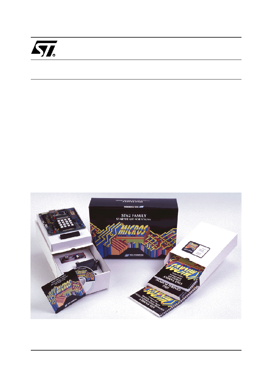
ST624XB-KIT
STARTER KIT FOR ST624x MCU FAMILY
HARDWARE FEATURES
s
Immediate evaluation of ST6240 with demon-
stration examples
s
Program debugging within the user's real appli-
cation environment
s
On board programming of ST62E46 and ST62T46
s
In-circuit programming of ST62E4x and ST62T4x
devices on the user's application board
SOFTWARE FEATURES
s
Software simulator including LCD display and I/
O read/write
s
Assembler, linker, debugger
s
EPROM/OTP programming utilities
s
Application examples
733
2/4
ST624XB-KIT
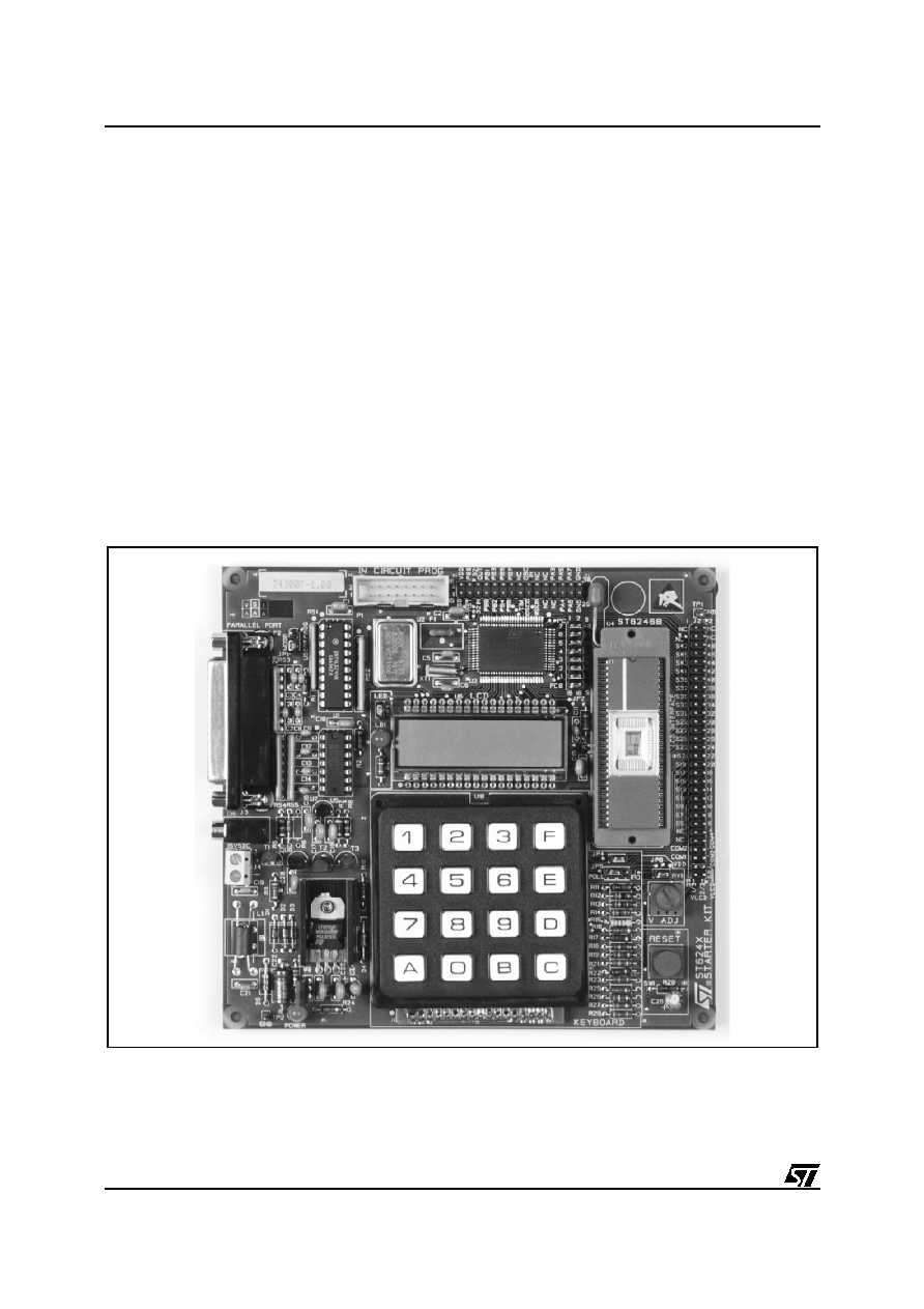
The Starter Kit Board
The Starter Kit board includes the following re-
sources:
∑
A Reset button.
∑
An 8-alphanumeric digit LCD.
∑
A hexadecimal keyboard.
∑
A LED indicator.
∑
A resistance trimmer.
∑
One 8 MHz and one 32 KHz oscillator.
∑
A SDIP56 ZIF socket to program the
ST62E46B or ST62T46B.
It comes with its own power supply unit that can be
plugged into an AC mains source, or a DC source
with the following characteristics:
∑
Voltage: 16V min./20V max.
∑
Current: 100 mA min.
It includes the following connectors:
∑
A parallel port connector (P2) for connection to
the host PC when it is used as a hardware sim-
ulator or for programming.
∑
A remote resource I/O interface (J1).
∑
An in-circuit ST6 programming board connec-
tor (P1).
∑
A remote LCD connector (J2) to which you can
connect your own LCD.
734
3/4
ST624XB-KIT
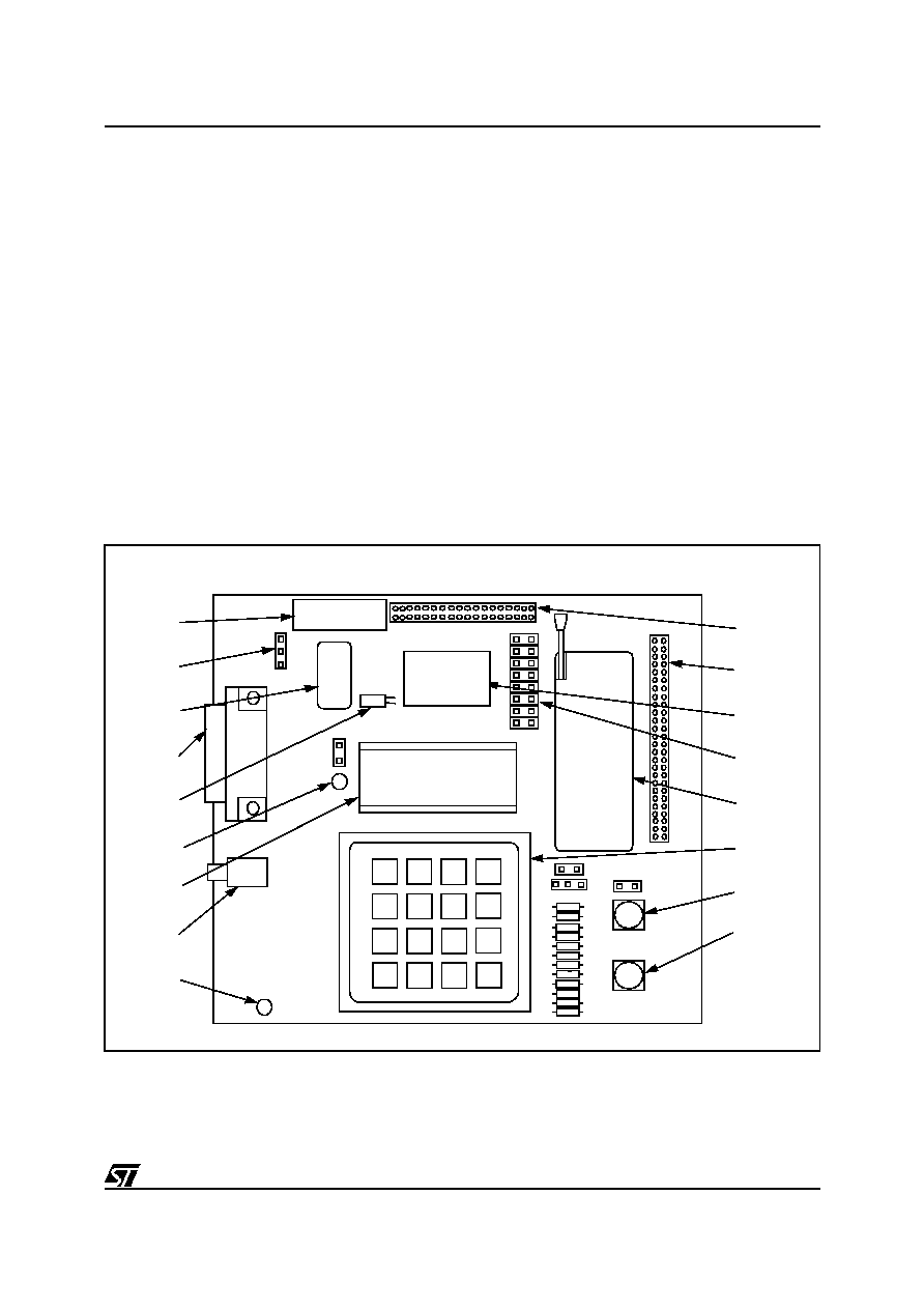
The following diagram shows the layout of the Starter Kit board.
1
In-circuit programming connector P1.
17
Remote resource I/O interface J1.
2
"Programming" or "User" operating mode
selection jumper JP1.
16
Remote LCD interface connector J2.
3
8 Mhz oscillator.
15
ST62T40B MCU
4
PC connector P2.
14
LCD protection with jumper JP2 if the combi-
port PC0-7 is used.
5
32.768 KHz oscillator.
13
SDIP56 ZIF MCU socket.
6
LED indicator LD1.
12
Keyboard
7
LCD display.
11
Voltage trimmer
8
Power supply JACK connector J3.
10
RESET button.
9
Power supply LED indicator LD2.
1
2
3
4
5
6
7
8
9
11
12
13
14
15
16
JP1
17
ST6246B
ST62T40B
SOCKET
DISPLAY
10
F
E
6
5
4
7
8
9
D
C
B
0
A
3
2
1
735
4/4
ST624XB-KIT
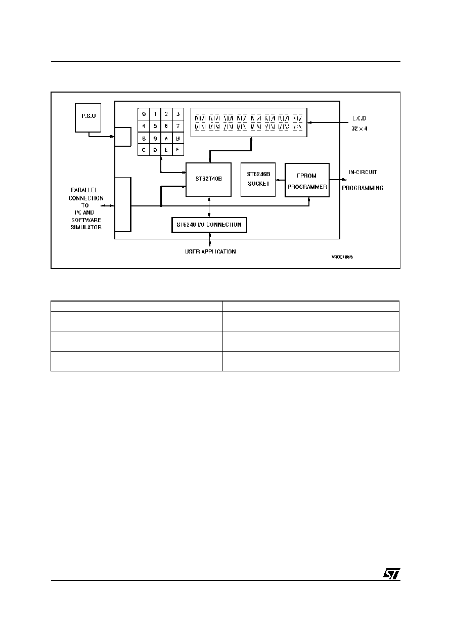
Figure 2. Block Diagram of the Starter Kit board
∑
ORDERING INFORMATION
Information furnished is believed to be accurate and reliable. However, STMicroelectronics assumes no responsibility for the consequences
of use of such information nor for any infringement of patents or other rights of third parties which may result from its use. No license is granted
by implication or otherwise under any patent or patent rights of STMicroelectronics. Specifications mentioned in this publication are subject
to change without notice. This publication supersedes and replaces all information previously supplied. STMicroelectronics products are not
authorized for use as critical components in life support devices or systems without the express written approval of STMicroelectronics.
The ST logo is a registered trademark of STMicroelectronics
©
1998 STMicroelectronics - All Rights Reserved.
Purchase of I
2
C Components by STMicroelectronics conveys a license under the Philips I
2
C Patent. Rights to use these components in an
I
2
C system is granted provided that the system conforms to the I
2
C Standard Specification as defined by Philips.
STMicroelectronics Group of Companies
Australia - Brazil - Canada - China - France - Germany - Italy - Japan - Korea - Malaysia - Malta - Mexico - Morocco - The Netherlands -
Singapore - Spain - Sweden - Switzerland - Taiwan - Thailand - United Kingdom - U.S.A.
http://www.st.com
Sales Type
Description
ST624XB-KIT/UK
Starter Kit for ST624x MCUs for operation in
United Kingdom
ST624XB-KIT/110
Starter Kit for ST624x MCUs for operation from
110 Vac mains
ST624XB-KIT/220
Starter Kit for ST624x MCUs for operation from
220 Vac mains
736