December 1997
1/84
This is preliminary information on a new product in development or undergoing evaluation. Details are subject to change without notice.
R
Rev. 2.2
ST6365, ST6375, ST6385
ST6367, ST6377, ST6387
8-BIT MCUs WITH
ON-SCREEN-DISPLAY FOR TV TUNING
s
4.5 to 6V supply operating range
s
8MHz Maximum Clock Frequency
s
User Program ROM: up to 20140 bytes
s
Reserved Test ROM: up to 340 bytes
s
Data ROM: user selectable size
s
Data RAM: 256 bytes
s
Data EEPROM: 384 bytes
s
42-Pin Shrink Dual in Line Plastic Package
s
Up to 22 software programmable general
purpose Inputs/Outputs, including 2 direct LED
driving Outputs
s
Two Timers each including an 8-bit counter with
a 7-bit programmable prescaler
s
Digital Watchdog Function
s
Serial Peripheral Interface (SPI) supporting S-
BUS/ I 2 C BUS and standard serial protocols
s
SPI for external frequency synthesis tuning
s
14 bit counter for voltage synthesis tuning
s
Up to Six 6-Bit PWM D/A Converters
s
AFC A/D converter with 0.5V resolution
s
Five interrupt vectors (IRIN/NMI, Timer 1 & 2,
VSYNC, PWR INT.)
s
On-chip clock oscillator
s
5 Lines by 15 Characters On-Screen Display
Generator with 128 Characters
s
All ROM types are supported by pin-to-pin
EPROM and OTP versions.
s
The development tool of the ST6365, ST6375,
ST6385, ST6367, ST6377, ST6387 microcon-
trollers consists of the ST638X-EMU2 emula-
tion and development system to be connected
via a standard RS232 serial line to an MS-DOS
Personal Computer.
DEVICE SUMMARY
DEVICE
ROM
(Bytes)
D/A Converter
ST6365
8K
4
ST6367
8K
6
ST6375
14K
4
ST6377
14K
6
ST6385
20K
4
ST6387
20K
6
PSDIP42
(Refer to end of Document for Ordering Information)
1

2/84
Table of Contents
84
1
ST6365, ST6375, ST6385, ST6367, ST6377, ST6387 . . . . . . . . 1
1 GENERAL DESCRIPTION . . . . . . . . . . . . . . . . . . . . . . . . . . . . . . . . . . . . . . . . . . . . . . . . . . . . . . 5
1.1 INTRODUCTION . . . . . . . . . . . . . . . . . . . . . . . . . . . . . . . . . . . . . . . . . . . . . . . . . . . . . . . . . 5
1.2 PIN DESCRIPTION . . . . . . . . . . . . . . . . . . . . . . . . . . . . . . . . . . . . . . . . . . . . . . . . . . . . . . . 7
1.3 MEMORY SPACES . . . . . . . . . . . . . . . . . . . . . . . . . . . . . . . . . . . . . . . . . . . . . . . . . . . . . . . 9
1.3.1 Stack Space . . . . . . . . . . . . . . . . . . . . . . . . . . . . . . . . . . . . . . . . . . . . . . . . . . . . . . . . 9
1.3.2 Program Space . . . . . . . . . . . . . . . . . . . . . . . . . . . . . . . . . . . . . . . . . . . . . . . . . . . . . 9
1.3.3 Data Space . . . . . . . . . . . . . . . . . . . . . . . . . . . . . . . . . . . . . . . . . . . . . . . . . . . . . . . 11
1.3.4 Data RAM/EEPROM/OSD RAM Addressing . . . . . . . . . . . . . . . . . . . . . . . . . . . . . . 13
2 CENTRAL PROCESSING UNIT . . . . . . . . . . . . . . . . . . . . . . . . . . . . . . . . . . . . . . . . . . . . . . . . . 16
2.1 INTRODUCTION . . . . . . . . . . . . . . . . . . . . . . . . . . . . . . . . . . . . . . . . . . . . . . . . . . . . . . . . 16
2.2 CPU REGISTERS . . . . . . . . . . . . . . . . . . . . . . . . . . . . . . . . . . . . . . . . . . . . . . . . . . . . . . . 16
3 CLOCKS, RESET, INTERRUPTS AND POWER SAVING MODES . . . . . . . . . . . . . . . . . . . . . 18
3.1 ON-CHIP CLOCK OSCILLATOR . . . . . . . . . . . . . . . . . . . . . . . . . . . . . . . . . . . . . . . . . . . . 18
3.2 RESETS . . . . . . . . . . . . . . . . . . . . . . . . . . . . . . . . . . . . . . . . . . . . . . . . . . . . . . . . . . . . . . . 19
3.2.1 RESET Input . . . . . . . . . . . . . . . . . . . . . . . . . . . . . . . . . . . . . . . . . . . . . . . . . . . . . . 1 9
3.2.2 Power-on Reset . . . . . . . . . . . . . . . . . . . . . . . . . . . . . . . . . . . . . . . . . . . . . . . . . . . . 19
3.2.3 Watchdog Reset . . . . . . . . . . . . . . . . . . . . . . . . . . . . . . . . . . . . . . . . . . . . . . . . . . . 20
3.2.4 Application Note . . . . . . . . . . . . . . . . . . . . . . . . . . . . . . . . . . . . . . . . . . . . . . . . . . . . 2 0
3.2.5 MCU Initialization Sequence . . . . . . . . . . . . . . . . . . . . . . . . . . . . . . . . . . . . . . . . . . 20
3.3 HARDWARE ACTIVATED DIGITAL WATCHDOG FUNCTION . . . . . . . . . . . . . . . . . . . . 21
3.4 INTERRUPT . . . . . . . . . . . . . . . . . . . . . . . . . . . . . . . . . . . . . . . . . . . . . . . . . . . . . . . . . . . . 23
3.4.1 Interrupt Vectors/Sources . . . . . . . . . . . . . . . . . . . . . . . . . . . . . . . . . . . . . . . . . . . . 23
3.4.2 Interrupt Priority . . . . . . . . . . . . . . . . . . . . . . . . . . . . . . . . . . . . . . . . . . . . . . . . . . . . 23
3.4.3 Interrupt Option Register . . . . . . . . . . . . . . . . . . . . . . . . . . . . . . . . . . . . . . . . . . . . . 24
3.4.4 Interrupt Procedure . . . . . . . . . . . . . . . . . . . . . . . . . . . . . . . . . . . . . . . . . . . . . . . . . 24
3.4.5 ST638x Interrupt Details . . . . . . . . . . . . . . . . . . . . . . . . . . . . . . . . . . . . . . . . . . . . . 25
3.5 POWER SAVING MODES . . . . . . . . . . . . . . . . . . . . . . . . . . . . . . . . . . . . . . . . . . . . . . . . . 26
3.5.1 WAIT Mode . . . . . . . . . . . . . . . . . . . . . . . . . . . . . . . . . . . . . . . . . . . . . . . . . . . . . . . 26
3.5.2 STOP Mode . . . . . . . . . . . . . . . . . . . . . . . . . . . . . . . . . . . . . . . . . . . . . . . . . . . . . . . 26
3.5.3 Exit from WAIT Mode . . . . . . . . . . . . . . . . . . . . . . . . . . . . . . . . . . . . . . . . . . . . . . . . 26
4 ON-CHIP PERIPHERALS . . . . . . . . . . . . . . . . . . . . . . . . . . . . . . . . . . . . . . . . . . . . . . . . . . . . . . 27
4.1 I/O PORTS . . . . . . . . . . . . . . . . . . . . . . . . . . . . . . . . . . . . . . . . . . . . . . . . . . . . . . . . . . . . . 27
4.1.1 Details of I/O Ports . . . . . . . . . . . . . . . . . . . . . . . . . . . . . . . . . . . . . . . . . . . . . . . . . . 28
4.1.2 I/O Pin Programming . . . . . . . . . . . . . . . . . . . . . . . . . . . . . . . . . . . . . . . . . . . . . . . . 30
4.1.3 Input/Output Configurations . . . . . . . . . . . . . . . . . . . . . . . . . . . . . . . . . . . . . . . . . . . 30
4.1.4 I/O Port Registers . . . . . . . . . . . . . . . . . . . . . . . . . . . . . . . . . . . . . . . . . . . . . . . . . . 30
4.2 TIMERS . . . . . . . . . . . . . . . . . . . . . . . . . . . . . . . . . . . . . . . . . . . . . . . . . . . . . . . . . . . . . . . 31
4.2.1 Timer Operating Modes . . . . . . . . . . . . . . . . . . . . . . . . . . . . . . . . . . . . . . . . . . . . . . 32
4.2.2 Timer Status Control Registers (TSCR) . . . . . . . . . . . . . . . . . . . . . . . . . . . . . . . . . . 33
4.2.3 Timer Counter Registers (TCR) . . . . . . . . . . . . . . . . . . . . . . . . . . . . . . . . . . . . . . . . 33
4.2.4 Timer Prescaler Registers (PSCR) . . . . . . . . . . . . . . . . . . . . . . . . . . . . . . . . . . . . . 33

3/84
Table of Contents
1
4.3 SERIAL PERIPHERAL INTERFACE . . . . . . . . . . . . . . . . . . . . . . . . . . . . . . . . . . . . . . . . . 34
4.3.1 S-BUS/I
2
C BUS Protocol Information . . . . . . . . . . . . . . . . . . . . . . . . . . . . . . . . . . . 34
4.3.2 S-BUS/I
2
C BUS Timing Diagrams . . . . . . . . . . . . . . . . . . . . . . . . . . . . . . . . . . . . . . 37
4.3.3 Compatibility S-BUS/I
2
C BUS . . . . . . . . . . . . . . . . . . . . . . . . . . . . . . . . . . . . . . . . . 39
4.3.4 STD SPI Protocol (Shift Register) . . . . . . . . . . . . . . . . . . . . . . . . . . . . . . . . . . . . . . 40
4.3.5 SPI Data/Control Register . . . . . . . . . . . . . . . . . . . . . . . . . . . . . . . . . . . . . . . . . . . . 40
4.4 14-BIT VOLTAGE SYNTHESIS TUNING PERIPHERAL . . . . . . . . . . . . . . . . . . . . . . . . . . 43
4.4.1 Output Details . . . . . . . . . . . . . . . . . . . . . . . . . . . . . . . . . . . . . . . . . . . . . . . . . . . . . 43
4.4.2 VS Tuning Cell Registers . . . . . . . . . . . . . . . . . . . . . . . . . . . . . . . . . . . . . . . . . . . . . 43
4.5 6-BIT PWM D/A CONVERTERS . . . . . . . . . . . . . . . . . . . . . . . . . . . . . . . . . . . . . . . . . . . . 44
4.6 AFC A/D COMPARATOR . . . . . . . . . . . . . . . . . . . . . . . . . . . . . . . . . . . . . . . . . . . . . . . . . 45
4.6.1 A/D Comparator . . . . . . . . . . . . . . . . . . . . . . . . . . . . . . . . . . . . . . . . . . . . . . . . . . . . 45
4.7 DEDICATED LATCHES . . . . . . . . . . . . . . . . . . . . . . . . . . . . . . . . . . . . . . . . . . . . . . . . . . . 46
4.8 ON-SCREEN DISPLAY (OSD) . . . . . . . . . . . . . . . . . . . . . . . . . . . . . . . . . . . . . . . . . . . . . 47
4.8.1 Format Specification . . . . . . . . . . . . . . . . . . . . . . . . . . . . . . . . . . . . . . . . . . . . . . . . 47
5 SOFTWARE . . . . . . . . . . . . . . . . . . . . . . . . . . . . . . . . . . . . . . . . . . . . . . . . . . . . . . . . . . . . . . . . 57
5.1 ST6 ARCHITECTURE . . . . . . . . . . . . . . . . . . . . . . . . . . . . . . . . . . . . . . . . . . . . . . . . . . . . 57
5.2 ADDRESSING MODES . . . . . . . . . . . . . . . . . . . . . . . . . . . . . . . . . . . . . . . . . . . . . . . . . . . 57
5.3 INSTRUCTION SET . . . . . . . . . . . . . . . . . . . . . . . . . . . . . . . . . . . . . . . . . . . . . . . . . . . . . . 58
6 ELECTRICAL CHARACTERISTICS . . . . . . . . . . . . . . . . . . . . . . . . . . . . . . . . . . . . . . . . . . . . . . 63
6.1 ABSOLUTE MAXIMUM RATINGS . . . . . . . . . . . . . . . . . . . . . . . . . . . . . . . . . . . . . . . . . . . 63
6.2 RECOMMENDED OPERATING CONDITIONS . . . . . . . . . . . . . . . . . . . . . . . . . . . . . . . . . 63
6.3 DC ELECTRICAL CHARACTERISTICS . . . . . . . . . . . . . . . . . . . . . . . . . . . . . . . . . . . . . . 64
6.4 AC ELECTRICAL CHARACTERISTICS . . . . . . . . . . . . . . . . . . . . . . . . . . . . . . . . . . . . . . 66
7 GENERAL INFORMATION . . . . . . . . . . . . . . . . . . . . . . . . . . . . . . . . . . . . . . . . . . . . . . . . . . . . . 67
7.1 PACKAGE MECHANICAL DATA . . . . . . . . . . . . . . . . . . . . . . . . . . . . . . . . . . . . . . . . . . . . 67
7.2 ORDERING INFORMATION . . . . . . . . . . . . . . . . . . . . . . . . . . . . . . . . . . . . . . . . . . . . . . . 67
7.3 CUSTOMER EEPROM INITIAL CONTENTS: . . . . . . . . . . . . . . . . . . . . . . . . . . . . . . . . . . 68
7.4 OSD TEST CHARACTER . . . . . . . . . . . . . . . . . . . . . . . . . . . . . . . . . . . . . . . . . . . . . . . . . 68
7.5 ORDERING INFORMATION TABLE . . . . . . . . . . . . . . . . . . . . . . . . . . . . . . . . . . . . . . . . . 68

4/84
ST6365, ST6375, ST6385 ST6367, ST6377, ST6387
ST63E85, T85, ST63E87, T87 . . . . . . . . . . . . . . . . . . . . . . . . . . 71
1 GENERAL DESCRIPTION . . . . . . . . . . . . . . . . . . . . . . . . . . . . . . . . . . . . . . . . . . . . . . . . . . . . . 72
1.1 INTRODUCTION . . . . . . . . . . . . . . . . . . . . . . . . . . . . . . . . . . . . . . . . . . . . . . . . . . . . . . . . 72
1.2 PIN DESCRIPTION . . . . . . . . . . . . . . . . . . . . . . . . . . . . . . . . . . . . . . . . . . . . . . . . . . . . . . 74
1.3 EPROM/OTP DESCRIPTION . . . . . . . . . . . . . . . . . . . . . . . . . . . . . . . . . . . . . . . . . . . . . . 76
1.4 POWER ON RESET . . . . . . . . . . . . . . . . . . . . . . . . . . . . . . . . . . . . . . . . . . . . . . . . . . . . . 76
1.5 EPROM ERASING . . . . . . . . . . . . . . . . . . . . . . . . . . . . . . . . . . . . . . . . . . . . . . . . . . . . . . . 76
2 ELECTRICAL CHARACTERISTICS . . . . . . . . . . . . . . . . . . . . . . . . . . . . . . . . . . . . . . . . . . . . . . 77
2.1 ABSOLUTE MAXIMUM RATINGS . . . . . . . . . . . . . . . . . . . . . . . . . . . . . . . . . . . . . . . . . . . 77
2.2 RECOMMENDED OPERATING CONDITIONS . . . . . . . . . . . . . . . . . . . . . . . . . . . . . . . . . 77
2.3 DC ELECTRICAL CHARACTERISTICS . . . . . . . . . . . . . . . . . . . . . . . . . . . . . . . . . . . . . . 78
2.4 AC ELECTRICAL CHARACTERISTICS . . . . . . . . . . . . . . . . . . . . . . . . . . . . . . . . . . . . . . 80
3 GENERAL INFORMATION . . . . . . . . . . . . . . . . . . . . . . . . . . . . . . . . . . . . . . . . . . . . . . . . . . . . . 81
3.1 ORDERING INFORMATION . . . . . . . . . . . . . . . . . . . . . . . . . . . . . . . . . . . . . . . . . . . . . . . 81
3.2 CUSTOMER EEPROM INITIAL CONTENTS: FORMAT . . . . . . . . . . . . . . . . . . . . . . . . . . 81
3.3 OSD TEST CHARACTER . . . . . . . . . . . . . . . . . . . . . . . . . . . . . . . . . . . . . . . . . . . . . . . . . 81
3.4 PACKAGE MECHANICAL DATA . . . . . . . . . . . . . . . . . . . . . . . . . . . . . . . . . . . . . . . . . . . . 82
3.5 ORDERING INFORMATION TABLE . . . . . . . . . . . . . . . . . . . . . . . . . . . . . . . . . . . . . . . . . 84
5/84
ST6365, ST6375, ST6385 ST6367, ST6377, ST6387
1 GENERAL DESCRIPTION
1.1 INTRODUCTION
The ST6365,67,75,77,85,87 microcontrollers are
members of the 8-bit HCMOS ST638x family, a
series of devices specially oriented to TV applica-
tions. Different ROM size and peripheral configu-
rations are available to give the maximum applica-
tion and cost flexibility. All ST638x members are
based on a building block approach: a common
core is surrounded by a combination of on-chip pe-
ripherals (macrocells) available from a standard li-
brary. These peripherals are designed with the
same Core technology providing full compatibility
and short design time. Many of these macrocells
are specially dedicated to TV applications. The
macrocells of the ST638x family are: two Timer
peripherals each including an 8-bit counter with a
7-bit software programmable prescaler (Timer), a
digital hardware activated watchdog function (DH-
WD), a 14-bit voltage synthesis tuning peripheral,
a Serial Peripheral Interface (SPI), up to six 6-bit
PWM D/A converters, an AFC A/D converter with
0.5V resolution, an on-screen display (OSD) with
15 characters per line and 128 characters (in two
banks each of 64 characters). In addition the fol-
lowing memory resources are available: program
ROM (up to 20K), data RAM (256 bytes), EEP-
ROM (384 bytes). Refer to pin configurations fig-
ures and to ST638x device summary (
Table 1
) for
the definition of ST638x family members and a
summary of differences among the different types.
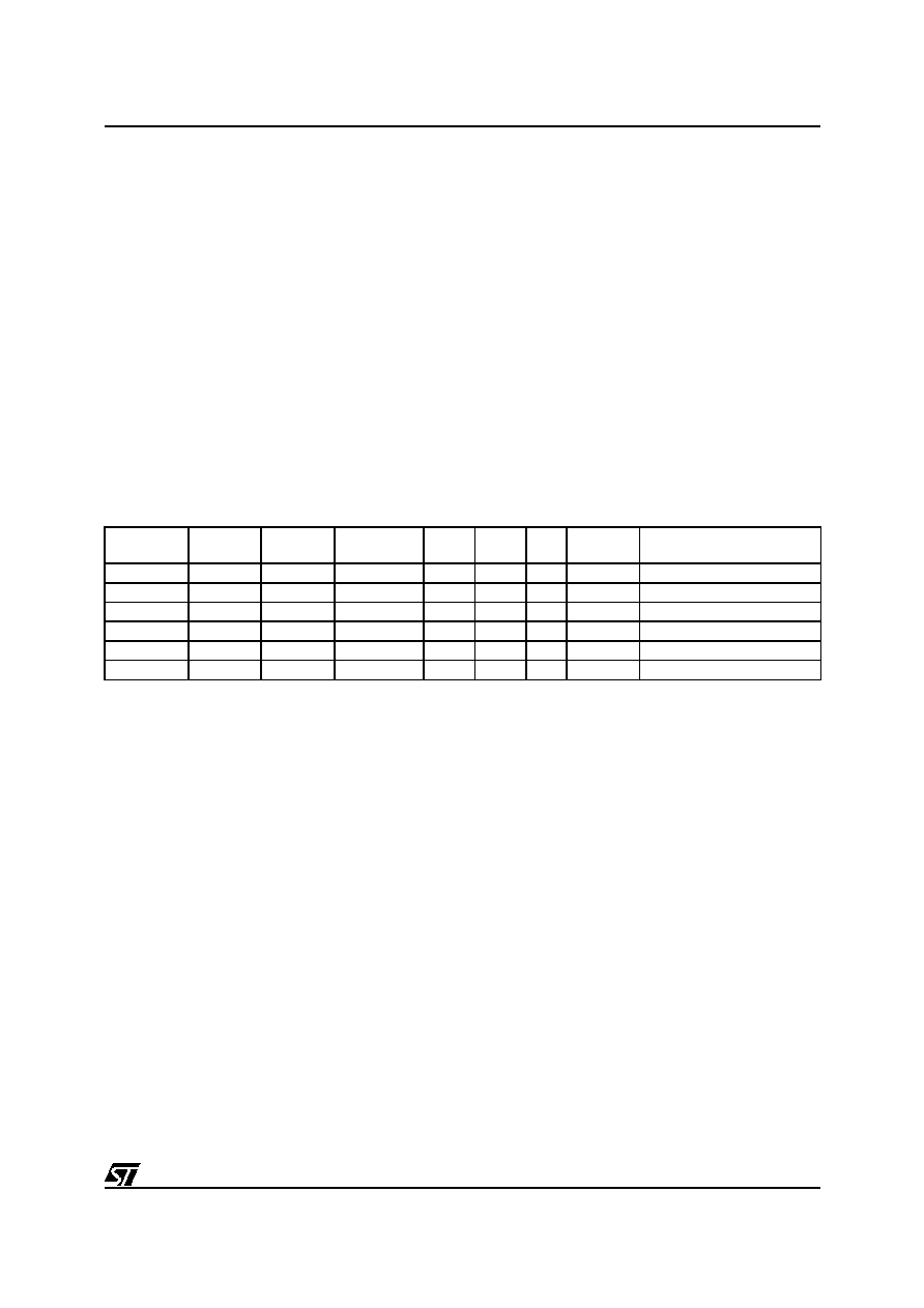
Table 1. Device Summary
Device
ROM
(Bytes)
RAM
(Bytes)
EEPROM
(Bytes)
AFC
VS
D/A
Colour
Pins
EPROM Devices
ST6365 8K 256 384
Yes
Yes
4
3
ST63E85
ST6367 8K 256 384
Yes
Yes
6
3
ST63E87
ST6375 14K 256 384
Yes
Yes
4 3
ST63E85
ST6377 14K 256 384
Yes
Yes
6 3
ST63E87
ST6385 20K 256 384
Yes
Yes
4 3
ST63E85
ST6387 20K 256 384
Yes
Yes
6 3
ST63E87