 | –≠–ª–µ–∫—Ç—Ä–æ–Ω–Ω—ã–π –∫–æ–º–ø–æ–Ω–µ–Ω—Ç: ST7291L3 | –°–∫–∞—á–∞—Ç—å:  PDF PDF  ZIP ZIP |
December 1997
1/5
This is preliminary information ona new product in development orundergoing evaluation. Details are subject to change without notice.
R
ST7291L
8-BIT MCU WITH 8/12/16/24 /32K ROM, TIMER, SUPPLY
SUPERVISOR AND CARRIER FREQUENCY GENERATOR
BRIEF DATA
s
2 to 5.5V Supply Operating Range
s
8MHz Maximum Clock Frequency
s
Fully Static Operation
s
0 to +70
∞
C Operating Temperature Range
s
Run, Wait, Stop and RAM Retention modes
s
User ROM: 12/16/24/ 32 Kbytes
s
Data RAM:
256/384 bytes
s
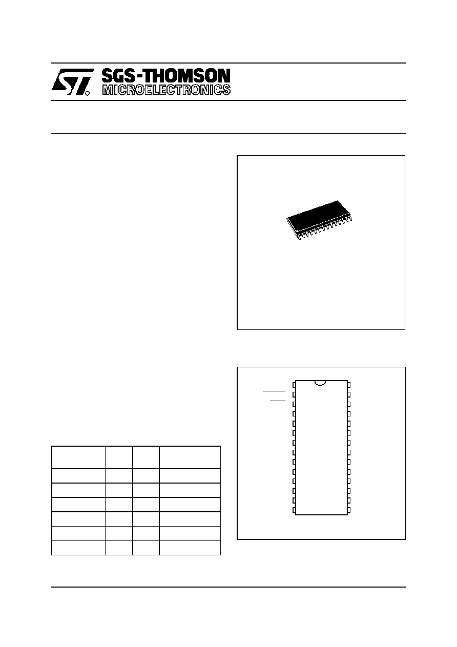
28 pin SO Plastic Packages
s
21 Bidirectional I/O lines
s
8 standard Push-pull I/Os with wake-up feature
13 standard Push-pull I/Os
s
16-bit Timer with Output Compare (no output
pin)
s
Low Voltage Detector (LVD)
s
Interrupt Wake-up function
s
IR Carrier Frequency Generator
s
8-bit Data Manipulation
s
63 Basic Instructions
s
17 main Addressing Modes
s
8x8 Unsigned Multiply instruction
s
True Bit Manipulation
s
Complete Development Support on PC/DOS/
Windows 3.1x/95/NT with Real-Time Emulator
s
Full
Software
Package
(Cross -Assembler,
Debugger)
s
Full Hardware Emulator
s
EPROM and OTP support
DEVICE SUMMARY
Note 1. This device is in development, consult your
SGS-TH OMSON representative for the current status.
Figure 1. Pin Description
Notes:
1. PC1 on ST7291L2/L3/L4; software selectable as OP on
ST7291L6/L5/L5A
DEVICE
ROM
(Bytes)
RAM
(Bytes)
CARRIER
GENERATOR
ST7291L6
(1)
32K
384
Yes
ST7291L5
24K
384
Yes
ST7291L5A
16K
384
Yes
ST7291L4
16K
256
No
ST7291L3
12K
256
No
ST7291L2
8K
256
No
PSO28
(See end of Datasheet for Ordering Information)
1
2
3
4
5
6
7
8
9
10
11
12
13
14
15
16
17
18
19
20
V
DD
RESET
WKP
PA7
PA6
PA1
PC0
PA5
PA4
PA3
OSCin
OSCout
PC1/OP
(1)
PC6
PC7
PB6
PB5
PB4
PB3
PB2
28
27
26
25
24
23
22
21
PA2
PA0
PB0
PB1
V
SS
TEST
PC5
PB7
1
2/5
ST7291L
1 GENERAL DESCRIPTION
1.1 INTRODUCTION
The ST7291L CMOS Microcontroller Unit is a
member of the ST7 family of microcontrollers. The
device is based on an industry-standard 8-bit core
and features an enhanced instruction set. Oscilla-
tor frequency may be as high as 8MHz, however,
thanks to the fully static design, operation is possi-
ble down to DC. Under software control, the
ST7291L may be placed in either WAIT or HALT
modes, thus reducing power consumption.
The enhanced instruction set and addressing
modes afford real programming potential. In addi-
tion to standard 8-bit data management, the
ST7291L features bit manipulation, 8x8 unsigned
multiplication and indirect addressing modes.
The device includes a CPU, ROM, RAM, I/O, an
on-chip oscillator, a timer with output compare
system and, depending on the version, a Low Volt-
age Detection (LVD) and Carrier Frequency gen-
eration for remote control applications.
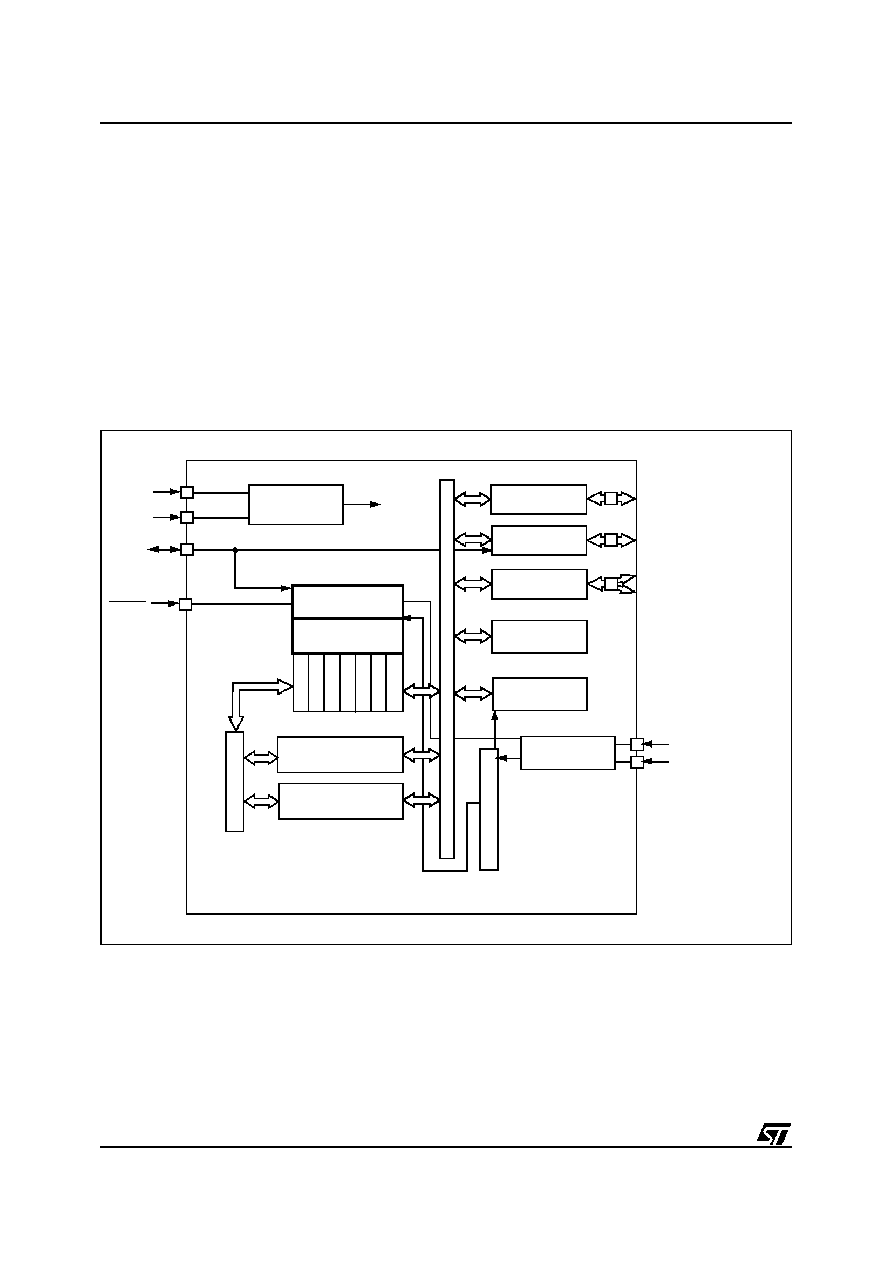
Figure 2. ST7291L Block Diagram
OSCILLATOR
A
DDRE
S
S
B
U
S
PORT A
PORT B
CARRIER FREQ.
8 BIT CORE
PA0..PA7 (8-bit)
PB0..PB7 (8-bit)
PC0, PC1, PC6, PC7
PORT C
V
DD
LOW VOLTAGE
DETECTOR
TIMER
SYSTEM
V
PP
PC5
PC
L
PC
H
SP
X
Y
A
CC
CONTRO L
Internal
CLOCK
ROM
8K/12K/16K/24K/32K
RAM
256/384
GENERATOR
OSCout
OSCin
WKP
RESET
DAT
A
B
US

December 1997
3/5
This is preliminary information ona new product in development orundergoing evaluation. Details are subject to change without notice.
R
ST72E91L
ST72T91L
8-BIT MCU WITH 32K EPROM/ OTP, TIMER, SUPPLY
SUPERVISOR AND CARRIER FREQUENCY GENERATOR
s
3 to 5.5V Supply Operating Range
s
8MHz Maximum Clock Frequency
s
Fully Static operation
s
0 to +70
∞
C Operating Temperature Range
(OTP)
s
Run, Wait, Stop and RAM Retention modes
s
User EPROM/ OTP: 32 Kbytes
s
Data RAM:
/384 Bytes
s
28 pin SO plastic packages for ST72T91 OTP
version
s
28 pin Ceramic SO package for ST72E91
EPROM version
s
21 Bidirectional I /O lines
s
8 Interrupt Wake-Up programmable input lines
s
16-bit Timer with Output Compare (no output
pin).
s
Interrupt Wake-up function
s
Low Voltage Detector (LVD)
s
IR Carrier Frequency Generator
s
8-bit Data Manipulation
s
63 Basic Instructions
s
17 main Addressing Modes
s
8x8 Unsigned Multiply instruction
s
True Bit Manipulation
s
Complete Development Support on PC/DOS/
Windows 3.1x/95/NT with Real-Time Emulator
s
Full
Software
Package
(Cross-Assembler,
Debugger)
s
Full Hardware Emulator
Figure 1. Pin Description
(See end of Datasheet for Ordering Information)
PSO28
CSO28W
1
2
3
4
5
6
7
8
9
10
11
12
13
14
15
16
17
18
19
20
V
DD
RESET
WKP
PA7
PA6
PA1
PC0
PA5
PA4
PA3
OSCin
OSCout
PC1/OP
PC6
PC7
PB6
PB5
PB4
PB3
PB2
28
27
26
25
24
23
22
21
PA2
PA0
PB0
PB1
V
SS
TEST/V
PP
PC5
PB7
4/5
ST72E91L ST72T91L
1 GENERAL DESCRIPTION
1.1 INTRODUCTION
The ST72E91 and ST72T91 devices form part of
the ST 7 family of Microcontrollers, designed and
produced by SGS-THOMSON Microelectronics
using an n-well proprietary HCMOS process. The
ST72E91 is equipped with internal EPROM mem-
ory and is available in windowed ceramic package,
whereas the ST72T91 OTP version is available in
a plastic package. The EPROM parts are fully
compatible with their ROM versions and the
present Datasheet will thus provide only informa-
tion specifically relating to the EPROM devices.
PLEASE REFER TO THE ST7291 DATASHEET
FOR THE ROM DEVICES FOR FULL DETAILS.
The ST72E91 is a user programmable and erasa-
ble device, best suited for development purposes.
The ST72T91 is a One-Time Programmable de-
vice (OTP) which offers the best cost/flexibility
trade-off for prototyping, pre-production and most
low to medium volume applications.
Both devices are based around an industry stand-
ard 8-bit core and offer an enhanced instruction
set. The processors will run at an 8MHz clock rate
with a 5V supply, and at up to 4MHz with a 3V
supply. Since the design is fully static, operation
down to DC is possible and the devices may be
placed in HALT or WAIT modes under program
control in order to reduce power requirements.
The powerful enhanced instruction set and ad-
dressing modes afford real programming potential.
In addition to standard 8-bit data management, the
ST72E91 and the ST72T91 feature true bit manip-
ulation, 8x8 unsigned multiplication and indirect
addressing modes. The devices include a CPU, an
on-chip oscillator, EPROM, RAM, I/O, and a timer
with output compare system.
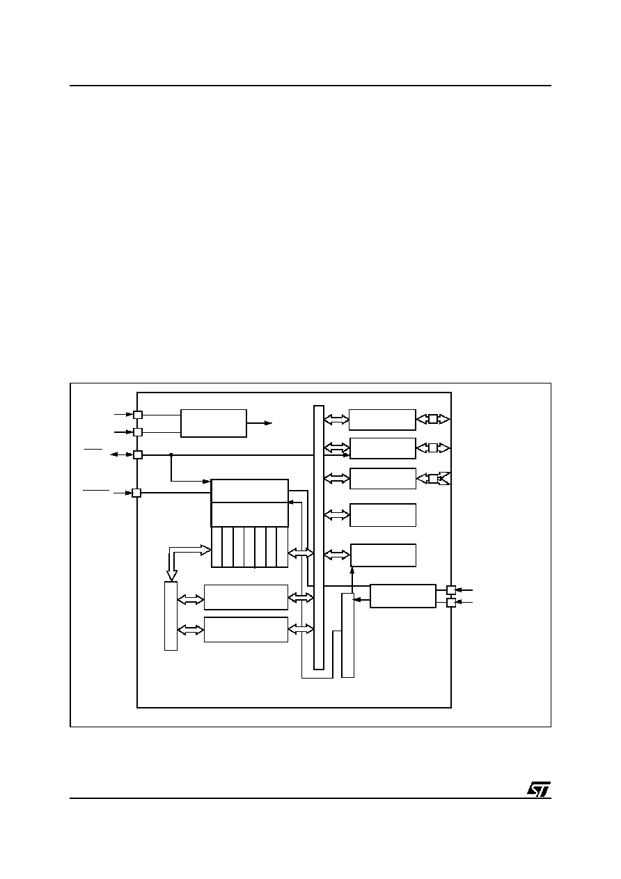
Figure 2. ST72E91 Block Diagram
OSCILLATOR
AD
D
R
ESS
BU
S
PORT A
PORT B
CARRIER FREQ.
8 BIT CORE
PA0..PA7 (8-bit)
PB0..PB7 (8-bit)
PC0,PC1,PC5,PC6,PC7
PORT C
V
DD
LOW VOLTAGE
DETECTOR
TIMER
SYSTEM
V
PP
PC
L
PC
H
SP
X
Y
A
CC
CONTR OL
Internal
CLOCK
EPROM/OTP
32K
RAM
256/384
GENERATOR
OSCout
OSCin
WKP
RESET
DAT
A
B
US

5/5
ST72E91L ST72T91L
Notes:
Information furnished is believed to be accurate and reliable. However, SGS-THOMSON Microelectronics assumes no
responsibility for the consequences of use of such information nor for any infringement of patents or other rights of third
parties which may result from its use. No license is granted by implication or otherwise under any patent or patent rights
of SGS-THOMSON Microelectronics. Specifications mentioned in this publication are subject to change without notice.
This publication supersedes and replaces all information previously supplied. SGS-THOMSON Microelectronics products
are not authorized for use as critical components in life support devices or systems without the express written approval
of SGS-THOMSON Microelectronics.
©
1997 SGS-THO MSON Microelectronics - All Rights Reserved.
Purchase of I
2
C Components by SGS-THOMSON Microelectronics conveys a license under the Philips I
2
C Patent. Rights to use these
components in an I
2
C system is granted provided that the system conforms to the I
2
C Standard Specification as defined by Philips.
SGS-THOMSON Microelectronics GROUP OF COMPANIES
Australia - Brazil - Canada - China - France - Germany - Italy - Japan - Korea - Malaysia - Malta - Morocco - The Netherlands - Singapore
Spain - Sweden - Switzerland - Taiwan - Thailand - United Kingdom - U.S.A.