 | –≠–ª–µ–∫—Ç—Ä–æ–Ω–Ω—ã–π –∫–æ–º–ø–æ–Ω–µ–Ω—Ç: STBR406 | –°–∫–∞—á–∞—Ç—å:  PDF PDF  ZIP ZIP |
1/4
STBR406/408
August 2001 - Ed: 4C
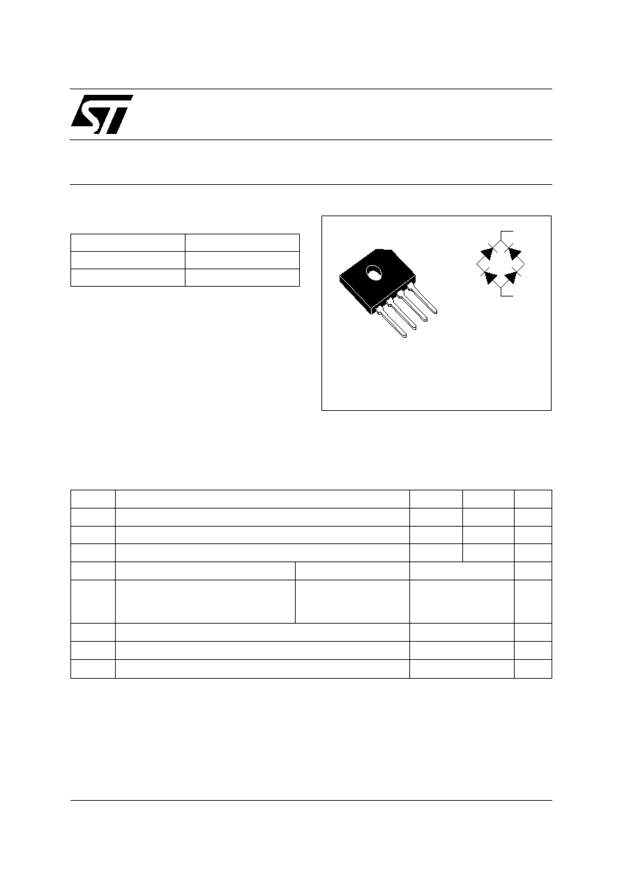
50-60Hz RECTIFICATION BRIDGE
Æ
Single-phase 4A Bridge for 50 & 60Hz rectification
in Switch Mode Power Supplies.
Application:
Home
appliances,
Automation,
Telecommunications, PC, Servers.
DESCRIPTION
s
Dielectric strength of 2000V
s
High Surge overload rating
s
High Surge current capability
s
UL94V0
s
Planar technology
FEATURES AND BENEFITS
I
F(AV)
4 A
V
RRM
600 V / 800 V
V
F
(max)
1.05 V
MAJOR PRODUCT CHARACTERISTICS
GBU
STBR406/408
-
+
~
~
Symbol
Parameter
STBR406 STBR408
Unit
V
RRM
Repetitive peak reverse voltage
600
800
V
V
RMS
RMS Voltage
420
560
V
V
DC
DC Blocking voltage
600
800
V
I
F(AV)
Average Forward Current
T
C
= 90∞C
4
A
I
FSM
Non repetitive surge peak forward
current
tp = 8.3 ms
Single sine wave
(JEDEC method)
120
A
I
2
t
Rating for Fusing (tp < 8.3ms)
60
A
2
S
Tj
Maximum operating junction temperature
150
∞C
T
stg
Storage temperature range
- 50 to 150
∞C
ABSOLUTE RATINGS (limiting values)
~
~
+
-
STBR406/408
2/4
Symbol
Parameter
Min.
Typ.
Max.
Unit
R
th(j-c)
Junction to case
7.6
8.4
∞C/W
R
th(j-a)
Junction to ambient
35
∞C/W
THERMAL PARAMETERS
Symbol
Parameter
Test conditions
Min.
Typ.
Max.
Unit
V
F
Forward voltage drop
I
F
= 4A
1.05
V
I
R
Reverse leakage current per
leg
V
R
= V
RRM
Tj = 25∞C
5
µ
A
Tj =125∞C
50
µ
A
C
Junction capacitance per leg
(note 1)
40
pF
Note 1: Measured at 1MHz and applied reverse voltage of 4V.
ELECTRICAL CHARACTERISTICS
0
1
2
3
4
5
6
7
8
0.0
0.5
1.0
1.5
2.0
2.5
3.0
3.5
4.0
IF(av)(A)
IP / IF(av)=20
IP / IF(av)=10
IP / IF(av)=5
(capacitive load)
IP / IF(av)=P
(resistive load)
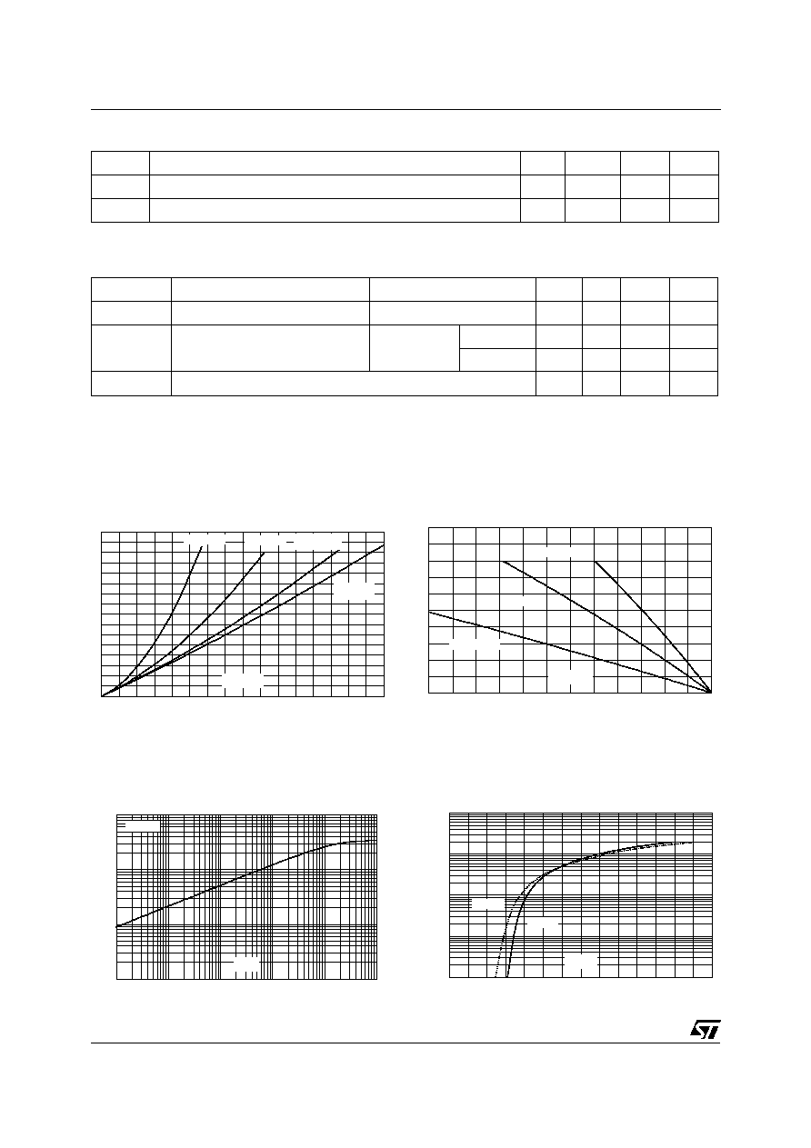
PF(av)(W)
Fig. 1: Average power dissipation of bridge versus
average output current.
0
1
2
3
4
5
0
25
50
75
100
125
150
Tamb(∞C)
Rth(j-a)=Rth(j-c)
Rth(j-a)=15∞C/W
Rth(j-a)=35∞C/W
IF(av)(A)
Fig. 2: Average output current versus ambient
temperature (resistive load or inductive load)
0.1
1.0
10.0
100.0
1.E-02
1.E-01
1.E+00
1.E+01
1.E+02
1.E+03
tp(s)
Free air
Zth(j-a)(∞C/W)
Fig. 3: Variation of thermal impedance junction to
ambient versus pulse duration (printed circuit
board epoxy FR4).
0.1
1.0
10.0
100.0
1000.0
0.0
0.5
1.0
1.5
2.0
2.5
3.0
3.5
VFM(V)
Tj=25∞C
Tj=125∞C
IFM(A)
Fig. 4: Forward voltage drop versus forward
current (typical values, per leg).
STBR406/408
3/4
1.E-05
1.E-04
1.E-03
1.E-02
1.E-01
1.E+00
1.E+01
0
100
200
300
400
500
600
700
800
VR(V)
Tj=150∞C
Tj=125∞C
Tj=75∞C
Tj=25∞C
IR(µA)
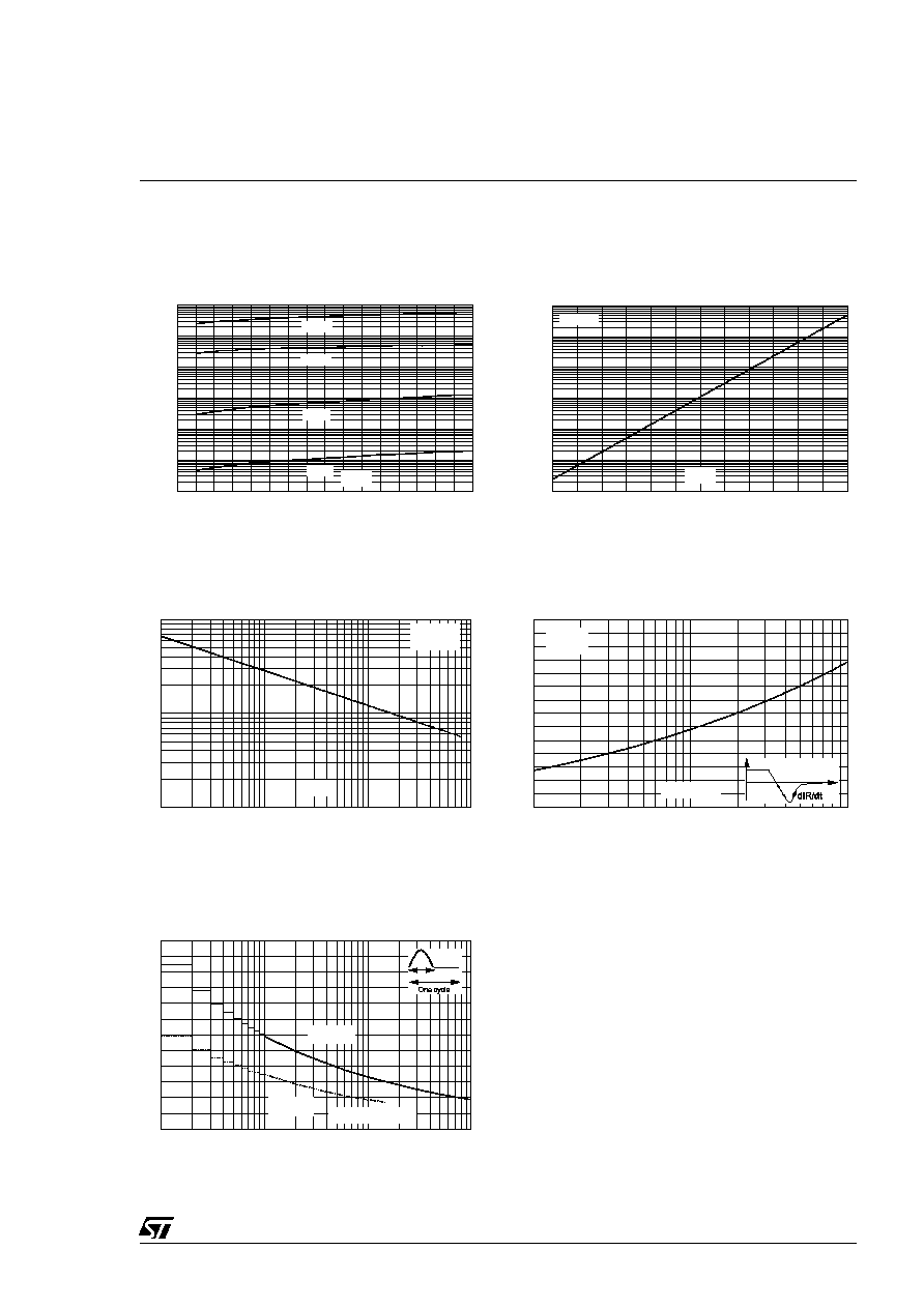
Fig. 5: Reverse leakage current versus reverse
voltage applied (typical values, per leg).
1.E-05
1.E-04
1.E-03
1.E-02
1.E-01
1.E+00
1.E+01
0
25
50
75
100
125
150
Tj(∞C)
VR=800V
IR(µA)
Fig. 6: Reverse leakage current versus junction
temperature (typical values).
1
10
100
1
10
100
1000
VR(V)
F=1MHz
Vosc=30mV
RMS
Tj=25∞C
C(pF)
Fig. 7: Junction capacitance versus reverse
voltage applied (typical values).
0.2
0.4
0.6
0.8
1.0
1.2
1.4
1.6
1
10
100
dIF/dt(A/µs)
IF=4A
VR=400V
Tj=125∞C
IF
dIF/dt
S=[dIF/dt]/[dIR/dt]
t
S(Softness factor)
Fig. 8: Softness factor versus dIF/dt (typical
values).
0
20
40
60
80
100
120
1
10
100
1000
Number of cycles
Non repetitive
Tj initial=150∞C
Repetitive
Tj initial=50∞C
tp=10ms
IFSM(A)
Fig. 9: Surge peak forward current versus number
of cycles (per leg).
STBR406/408
4/4
Information furnished is believed to be accurate and reliable. However, STMicroelectronics assumes no responsibility for the consequences of
use of such information nor for any infringement of patents or other rights of third parties which may result from its use. No license is granted by
implication or otherwise under any patent or patent rights of STMicroelectronics. Specifications mentioned in this publication are subject to
change without notice. This publication supersedes and replaces all information previously supplied.
STMicroelectronics products are not authorized for use as critical components in life support devices or systems without express written ap-
proval of STMicroelectronics.
The ST logo is a registered trademark of STMicroelectronics
© 2001 STMicroelectronics - Printed in Italy - All rights reserved.
STMicroelectronics GROUP OF COMPANIES
Australia - Brazil - China - Finland - France - Germany - Hong Kong - India - Italy - Japan - Malaysia
Malta - Morocco - Singapore - Spain - Sweden - Switzerland - United Kingdom - U.S.A.
http://www.st.com
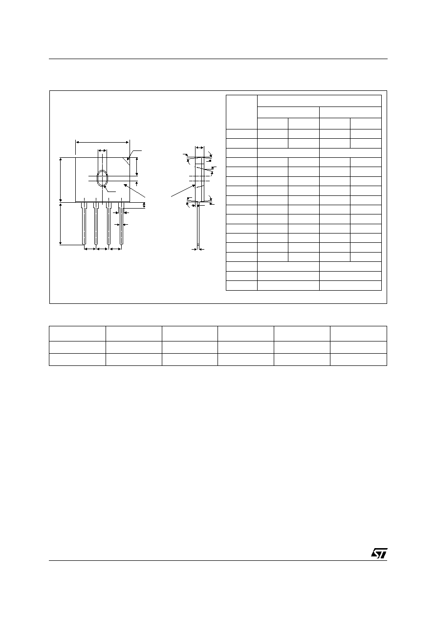
PACKAGE MECHANICAL DATA
GBU
B
D
I
H
G
ÿ
P
F
C
E
A
J
-
~
~
+
N
N
N
K
Q
M
O
O
O
L
O
Front Side
REF.
DIMENSIONS
Millimeters
Inches
Min.
Max.
Min.
Max.
A
21.8
22.3
0.86
0.88
B
18.3
18.8
0.72
0.74
C
3.2 typ. 45∞
0.125 typ. 45∞
D
17.5
18
0.69
0.71
E
7.4
7.9
0.29
0.31
F
1.65
2.16
0.065
0.085
G
2.25
2.75
0.089
0.108
H
1.95
2.35
0.077
0.093
I
1.02
1.27
0.04
0.05
J
3.5
4.1
0.14
0.16
K
3.3
3.56
0.13
0.14
L
0.76
1
0.03
0.04
M
0.46
0.56
0.018
0.022
N
4.83
5.33
0.19
0.21
O
7∞ typ.
7∞ typ.
P
1.9 typ.
0.075 typ.
Q
7∞ typ.
7∞ typ.
Ordering type
Marking
Package
Weight
Base qty
Delivery mode
STBR406
STBR406
GBU
4.0g
20
Tube
STBR408
STBR408
GBU
4.0g
20
Tube
s
Epoxy meets UL94,V0
s
Cooling method: C
s
Recommended torque value: 0.8 m.N
s
Maximum torque value: 1.0 m.N