 | ÐлекÑÑоннÑй компоненÑ: STFPC311 | СкаÑаÑÑ:  PDF PDF  ZIP ZIP |
Äîêóìåíòàöèÿ è îïèñàíèÿ www.docs.chipfind.ru
May 2006
Rev 1
1/39
39
STFPC311
Front panel controller/driver
with standby power management
Features
IC front panel controller/driver
Timing power standby management controller
IC power supply from 3.3V (V
DD
) to 30V (V
SS
)
Integrated VFD driver and controller
Infrared (IR) Remote Control (RC) Decoder
(Philips or NEC format)
Drives many display modes (12 segments/16
digits to 20 segments/8 digits)
High voltage outputs (V
DD
- 33.3V max)
No external resistors necessary for driver
outputs (P-channel open- drain with pull-down
resistor outputs)
Key scanning (up to 12mm x 2mm matrix)
Led ports (4 channels, 20mA, max)
Serial interface (STB, CLK, D
IN
, and D
OUT
)
communication protocol
Dimming circuit (adjustable up to 8 steps)
Supports auto-increment of display digit, which
lightens the load on the MCU
Programmable 8 hot keys for the IR remote
control command
Programmable 8 hot keys for key scan
command
Low power consumption in standby mode
2 general purpose input ports (SW1, SW2)
Available in PQFP-52 package
Description
The STFPC311 is a complete, low-cost,
integrated solution for controlling and driving a
front panel Vacuum Fluorescent Display (VFD). It
is ideal for decreasing power consumption in
standby mode by reducing the application standby
current to a minimum. It also contains a built-in
remote control decoder module.
While in the standby mode of operation, a valid
key press or signal from infrared decoder will start
a proper power-up see
Figure 6 on page 12
.
The STFPC311 integrates a VFD controller with a
driver that is run on a 1/8 to 1/16-duty factor. It
consists of 12 segments output lines, 8 grid output
lines, 8 shared segments/grid output drive lines, a
display memory, a control circuit, and a key scan
circuit. Serial data is input to the STFPC311
through the SPI Interface of a microcontroller
(STB, D
IN
, D
OUT
, and CLK).
Additionally, this IC can support 2 general
purpose input switches (SW1 and SW2).
Features
DVD players
VCD players
AV equipment like Home Stereo
POS Systems
PQFP-52
www.st.com
Order Codes
Part number
Temperature range
Package
STFPC311
-40 to 85°C
PQFP-52

STFPC311
2/39
Contents
1
Functional description . . . . . . . . . . . . . . . . . . . . . . . . . . . . . . . . . . . . . . . . . 4
1.1
Block diagram . . . . . . . . . . . . . . . . . . . . . . . . . . . . . . . . . . . . . . . . . . . . . . . . . 4
2
Pin connection . . . . . . . . . . . . . . . . . . . . . . . . . . . . . . . . . . . . . . . . . . . . . . . . 5
2.1
Pin description . . . . . . . . . . . . . . . . . . . . . . . . . . . . . . . . . . . . . . . . . . . . . . . . 6
3
Initialization . . . . . . . . . . . . . . . . . . . . . . . . . . . . . . . . . . . . . . . . . . . . . . . . . . 7
3.1
Normal mode of operation . . . . . . . . . . . . . . . . . . . . . . . . . . . . . . . . . . . . . . . 7
3.2
Receive operation . . . . . . . . . . . . . . . . . . . . . . . . . . . . . . . . . . . . . . . . . . . . . . 7
3.3
Transmit operation . . . . . . . . . . . . . . . . . . . . . . . . . . . . . . . . . . . . . . . . . . . . . 7
3.4
Standby or power-down mode . . . . . . . . . . . . . . . . . . . . . . . . . . . . . . . . . . . . 8
3.5
IR Decoding . . . . . . . . . . . . . . . . . . . . . . . . . . . . . . . . . . . . . . . . . . . . . . . . . . 8
3.6
Watchdog timer . . . . . . . . . . . . . . . . . . . . . . . . . . . . . . . . . . . . . . . . . . . . . . . . 8
3.6.1
Watchdog timer operation during power-up . . . . . . . . . . . . . . . . . . . . . . . . . . . 9
3.6.2
Watchdog timer operation during power-down . . . . . . . . . . . . . . . . . . . . . . . 10
3.6.3
Watchdog timer operation during standby . . . . . . . . . . . . . . . . . . . . . . . . . . . 11
3.7
Flow charts . . . . . . . . . . . . . . . . . . . . . . . . . . . . . . . . . . . . . . . . . . . . . . . . . 12
4
Display RAM address and display mode . . . . . . . . . . . . . . . . . . . . . . . . . . 15
5
Data . . . . . . . . . . . . . . . . . . . . . . . . . . . . . . . . . . . . . . . . . . . . . . . . . . . . . . . . 17
5.1
LED Port . . . . . . . . . . . . . . . . . . . . . . . . . . . . . . . . . . . . . . . . . . . . . . . . . . . . 17
5.2
SW Data . . . . . . . . . . . . . . . . . . . . . . . . . . . . . . . . . . . . . . . . . . . . . . . . . . . . 17
6
Commands . . . . . . . . . . . . . . . . . . . . . . . . . . . . . . . . . . . . . . . . . . . . . . . . . . 18
6.1
Configuration mode setting command . . . . . . . . . . . . . . . . . . . . . . . . . . . . . 18
6.2
Data setting command . . . . . . . . . . . . . . . . . . . . . . . . . . . . . . . . . . . . . . . . . 19
6.3
Address setting command . . . . . . . . . . . . . . . . . . . . . . . . . . . . . . . . . . . . . . 20
6.4
Display control and hotkey setting command . . . . . . . . . . . . . . . . . . . . . . . . 20
7
Programmable hotkeys . . . . . . . . . . . . . . . . . . . . . . . . . . . . . . . . . . . . . . . . 22
7.1
IR Remote control . . . . . . . . . . . . . . . . . . . . . . . . . . . . . . . . . . . . . . . . . . . . . 22
7.2
Front panel keys . . . . . . . . . . . . . . . . . . . . . . . . . . . . . . . . . . . . . . . . . . . . . . 22

STFPC311
3/39
8
Default status . . . . . . . . . . . . . . . . . . . . . . . . . . . . . . . . . . . . . . . . . . . . . . . . 24
8.1
Power-up default status . . . . . . . . . . . . . . . . . . . . . . . . . . . . . . . . . . . . . . . . . 24
8.2
STANDBY status . . . . . . . . . . . . . . . . . . . . . . . . . . . . . . . . . . . . . . . . . . . . . . 24
9
Remote control protocols . . . . . . . . . . . . . . . . . . . . . . . . . . . . . . . . . . . . . . 25
9.1
RC-5 remote control . . . . . . . . . . . . . . . . . . . . . . . . . . . . . . . . . . . . . . . . . . . 25
9.2
SPI interface IR data transmission . . . . . . . . . . . . . . . . . . . . . . . . . . . . . . . . 26
9.3
NEC remote control . . . . . . . . . . . . . . . . . . . . . . . . . . . . . . . . . . . . . . . . . . . 26
10
Maximum rating . . . . . . . . . . . . . . . . . . . . . . . . . . . . . . . . . . . . . . . . . . . . . . 28
10.1
Power consumption estimation . . . . . . . . . . . . . . . . . . . . . . . . . . . . . . . . . . . 29
11
Electrical characteristics . . . . . . . . . . . . . . . . . . . . . . . . . . . . . . . . . . . . . . 30
12
Timing characteristics . . . . . . . . . . . . . . . . . . . . . . . . . . . . . . . . . . . . . . . . 31
13
Serial communication format . . . . . . . . . . . . . . . . . . . . . . . . . . . . . . . . . . . 32
14
Typical application diagram . . . . . . . . . . . . . . . . . . . . . . . . . . . . . . . . . . . . 35
15
Package mechanical data . . . . . . . . . . . . . . . . . . . . . . . . . . . . . . . . . . . . . . 36
16
Revision history . . . . . . . . . . . . . . . . . . . . . . . . . . . . . . . . . . . . . . . . . . . . . . 38

1 Functional description
STFPC311
4/39
1 Functional
description
The STFPC311 receives serial data from the microcontroller through the SPI interface, latches
the data, and then masks the inputs from the MCU. This data consists of commands followed
by data. There are 4 types of commands:
configuration,
data,
address, and
display.
The STFPC311 integrates the supply standby power management functionality, remote control
decoder, and a 28-bit VFD driver. Microcontrollers usually run the first two tasks.
This device reduces the stand-by power consumption of the whole Front Panel application as
well as the hardware by integrating the infrared (IR) remote control decoder.
A dedicated supply voltage powers the STFPC311 directly from the main supply board. When
power is plugged in, control of the power supply management is done using the following pins:
1. STBY,
2. IR_DATA_IN,
and
3. READY.
1.1 Block
diagram
Figure 1.
Block diagram
SEG13/GRID16
2
2
CLK
OSC
Display Memory
(20 x 16)
Timing Generator
Key Scan and
Dimming Circuit
20-bit
Output
Latch
16-bit
Shift
Register
Data
Selector
Se
gm
en
t
Dr
i
v
e
r
s
M
u
lt
ip
le
x
e
d
Dr
i
v
e
r
s
Gr
i
d
Dr
i
v
e
r
s
SPI
Serial
I/F
4-bit
Latch
Key Data Memory
(2 x 12)
KEY1
KEY2
20
12
8
8
8
8
16
LED2
LED1
V
DD
(+3.3V)
GND
(0V)
V
SS
(-30V)
GRID1
GRID8
SEG20/GRID9
SEG12/KS2
SEG1/KS1
V
DD
IR_DATA_IN
MUTE
STBY
R
OSC
Command Decoder
Remote Control
Decoder & Stand
By Function
READY/STBY_n
Watchdog
Timer
D
OUT
STB
LED3
LED4
2-bit
Latch
SW1
SW2
D
IN
2
2
CLK
OSC
Display Memory
(20 x 16)
Timing Generator
Key Scan and
Dimming Circuit
20-bit
Output
Latch
16-bit
Shift
Register
Data
Selector
Se
gm
en
t
Dr
i
v
e
r
s
M
u
lt
ip
le
x
e
d
Dr
i
v
e
r
s
Gr
i
d
Dr
i
v
e
r
s
SPI
Serial
I/F
4-bit
Latch
Key Data Memory
(2 x 12)
KEY1
KEY2
20
12
8
8
8
8
16
LED2
LED1
V
DD
(+3.3V)
GND
(0V)
V
SS
(-30V)
GRID1
GRID8
SEG20/GRID9
SEG12/KS2
SEG1/KS1
V
DD
IR_DATA_IN
MUTE
STBY
R
OSC
Command Decoder
Remote Control
Decoder & Stand
By Function
READY/STBY_n
Watchdog
Timer
D
OUT
STB
LED3
LED4
2-bit
Latch
SW1
SW2
D
IN
STFPC311
2 Pin connection
5/39
2 Pin
connection
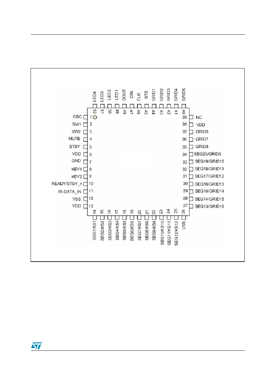
Note:
For a description of the behavior of each pin, refer to the
Table 1: Pin description on page 6
.
Figure 2.
Connection diagram (top view PQFP-52)
STFPC311
Document Outline