Æ
STPC CONSUMER-S
PC Compatible Embeded Microprocessor
ADVANCED DATA
1/51
29/10/99
Release B
This is preliminary information on a new product now in development or undergoing evaluation. Details are subject to change without notice.
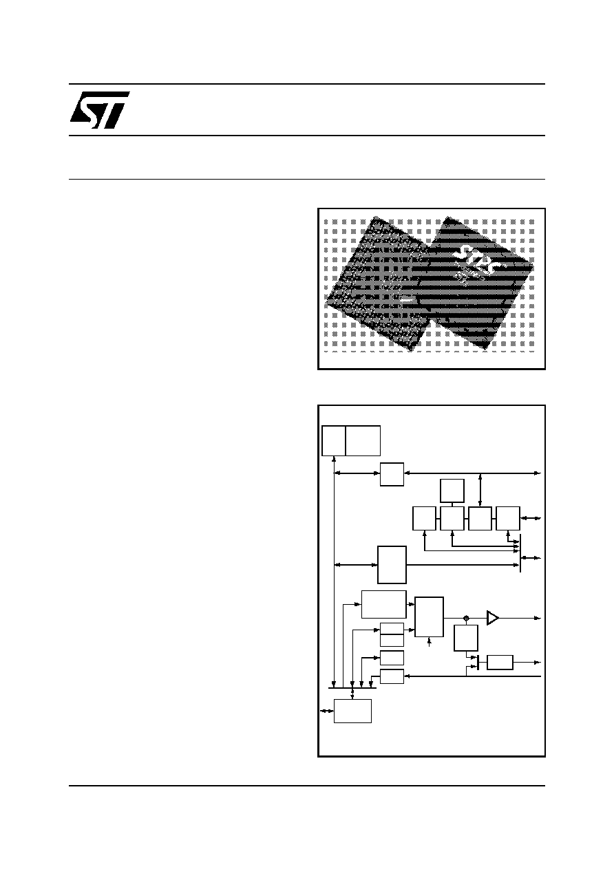
Figure 1. Logic Diagram
s
POWERFUL x86 PROCESSOR
s
64-BIT 66MHz SDRAM UMA CONTROLLER
s
VGA & SVGA CRT CONTROLLER
s
2D GRAPHICS ENGINE
s
VIDEO INPUT PORT
s
VIDEO PIPELINE
- UP-SCALER
- VIDEO COLOR SPACE CONVERTER
- CHROMA & COLOUR KEY SUPPORT
s
TV OUTPUT
- 3-LINE FLICKER FILTER
- CCIR 601/656 SCAN CONVERTER
- NTSC / PAL COMPOSITE, RGB, S-VIDEO
s
PCI MASTER / SLAVE CONTROLLER
s
ISA MASTER / SLAVE CONTROLLER
s
INTEGRATED PERIPHERAL CONTROLLER
- DMA CONTROLLER
- INTERRUPT CONTROLLER
- TIMER / COUNTERS
s
OPTIONAL 16-BIT LOCAL BUS INTERFACE
s
EIDE CONTROLLER
s
I C INTERFACE
s
POWER MANAGEMENT UNIT
s
3.3V OPERATION
STPC CONSUMER-S OVERVIEW
The STPC Consumer-S integrates a standard 5th
generation x86 core, a Synchronous DRAM con-
troller, a graphics subsystem, a video input port,
video pipeline, and support logic including PCI,
ISA, and IDE controllers to provide a single con-
sumer orientated PC compatible subsystem on a
single device.
The device is based on a tightly coupled Unified
Memory Architecture (UMA), sharing the same
memory array between the CPU main memory
and the graphics and video frame buffers.
The STPC Consumer-S is packaged in a 388
Plastic Ball Grid Array (PBGA).
PBGA388
x86
Core
Host
I/F
SDRAM
CTRL
SVGA
GE
VIP
PCI
m/s
LB
CTR
PCI Bus
ISA
m/s
IPC
PCI
m/s
ISA Bus
CRTC
Cursor
Moni tor
TV
IDE
I/F
PMU
W.dog
Video
Pipeline
C Key
K Key
LUT
Local Bus
Encoder
TVO

STPC CONSUMER-S
2/51
Release B
This is preliminary information on a new product now in development or undergoing evaluation. Details are subject to change without notice.
s
X86 Processor core
s
Fully static 32-bit 5-stage pipeline, x86
processor fully PC compatible.
s
Can access up to 4GB of external memory.
s
8Kbyte unified instruction and data cache
with write back and write through capability.
s
Parallel processing integral floating point unit,
with automatic power down.
s
Fully static design for dynamic clock control.
s
Low power and system management modes.
s
SDRAM Controller
s
64-bit data bus.
s
Up to 66MHz SDRAM clock speed.
s
Integrated system memory, graphic frame
memory and video frame memory.
s
Supports 2MB up to 128 MB memory.
s
Supports 8MB, 16M, and 32MB DIMMs.
s
Supports buffered, non buffered, and
registered DIMMs
s
4-line write buffers for CPU to DRAM and PCI
to DRAM cycles.
s
4-line read prefetch buffers for PCI masters.
s
Programmable latency
s
Programmable timing for DRAM parameters.
s
Supports -8, -10, -12, -13, -15 memory parts
s
Supports 1MB up to 8MB memory hole.
s
32-bit accesses not supported.
s
Autoprecharge not supported.
s
Power down not supported.
s
FPM and EDO not supported.
s
Graphics Controller
s
64-bit windows accelerator.
s
Compatibility to VGA & SVGA standards.
s
Hardware acceleration for text, bitblts,
transparent blts and fills.
s
Up to 64 x 64 bit graphics hardware cursor.
s
Up to 4MB long linear frame buffer.
s
8-, 16-, and 24-bit pixels.
s
CRT Controller
s
Integrated 135MHz triple RAMDAC allowing
for 1024 x 768 x 75Hz display.
s
8-, 16-, 24-bit pixels.
s
Interlaced or non-interlaced output.
s
Video Input port
s
Accepts video inputs in CCIR 601 mode.
s
Optional 2:1 decimator
s
Stores captured video in off setting area of
the onboard frame buffer.
s
Video pass through to the onchip PAL/NTSC
encoder for full screen video images.
s
HSYNC and B/T generation or lock onto
external video timing source.
s
Video Pipeline
s
Two-tap interpolative horizontal filter.
s
Two-tap interpolative vertical filter.
s
Color space conversion.
s
Programmable window size.
s
Chroma and color keying for integrated video
overlay.
s
TV Output
s
Programmable two tap filter with gamma
correction or three tap flicker filter.
s
Progressive to interlaced scan converter.
s
NTSC-M, PAL-M,PAL-B,D,G,H,I,PAL-N easy
programmable video outputs.
s
CCIR601 encoding with programmable color
subcarrier frequencies.
s
Line skip/insert capability
s
Interlaced or non-interlaced operation mode.
s
625 lines/50Hz or 525 lines/60Hz 8 bit
multiplexed CB-Y-CR digital input.
s
CVBS and R,G,B simultaneous analog
outputs through 10-bit DACs.
s
Cross color reduction by specific trap filtering
on luma within CVBS flow.
s
Power down mode available on each DAC.

STPC CONSUMER-S
3/51
Release B
This is preliminary information on a new product now in development or undergoing evaluation. Details are subject to change without notice.
s
PCI Controller
s
Fully compliant with PCI 2.1 specification.
s
Integrated PCI arbitration interface. Up to 3
masters can connect directly. External PAL
allows for greater than 3 masters.
s
Translation of PCI cycles to ISA bus.
s
Translation of ISA master initiated cycle to
PCI.
s
Support for burst read/write from PCI master.
s
PCI clock is 1/3 or 1/2 Host clock .
s
ISA master/slave controller
s
Generates the ISA clock from either
14.318MHz oscillator clock or PCI clock
s
Supports programmable extra wait state for
ISA cycles
s
Supports I/O recovery time for back to back I/
O cycles.
s
Fast Gate A20 and Fast reset.
s
Supports the single ROM that C, D, or E.
blocks shares with F block BIOS ROM.
s
Supports flash ROM.
s
Supports ISA hidden refresh.
s
Buffered DMA & ISA master cycles to reduce
bandwidth utilization of the PCI and Host bus.
NSP compliant.
s
Integrated Peripheral Controller
s
2X8237/AT compatible 7-channel DMA
controller.
s
2X8259/AT compatible interrupt Controller.
16 interrupt inputs - ISA and PCI.
s
Three 8254 compatible Timer/Counters.
s
Co-processor error support logic.
s
Supports external RTC.
s
Local Bus interface
s
Multiplxed with ISA interface.
s
Low latency bus
s
22-bit address bus.
s
16-bit data bus with word steering capability.
s
Programmable timing (Host clock granularity)
s
2 Programmable Flash Chip Select.
s
5 Programmable I/O Chip Select.
s
Supports 32-bit Flash burst.
s
2-level hardware key protection for Flash boot
block protection.
s
Supports 2 banks of 8MB flash devices with
boot block shadowed to 0x000F0000.
s
IDE Interface
s
Supports PIO and Bus Master IDE
s
Supports up to Mode 5 Timings
s
Transfer Rates to 22 MBytes/sec
s
Supports up to 4 IDE devices
s
Concurrent channel operation (PIO & DMA
modes) - 4 x 32-Bit Buffer FIFO per channel
s
Support for PIO mode 3 & 4.
s
Support for DMA mode 1 & 2.
s
Support for 11.1/16.6 MB/s, I/O Channel
Ready PIO data transfers.
s
Supports 13.3/16.6 MB/s DMA data transfers
s
Bus Master with scatter/gather capability
s
Multi-word DMA support for fast IDE drives
s
Individual drive timing for all four IDE devices
s
Supports both legacy & native IDE modes
s
Supports hard drives larger than 528MB
s
Support for CD-ROM and tape peripherals
s
Backward compatibility with IDE (ATA-1).
s
Power Management
s
Four power saving modes: On, Doze,
Standby, Suspend.
s
Programmable system activity detector
s
Supports SMM.
s
Supports STOPCLK.
s
Supports IO trap & restart.
s
Independent peripheral time-out timer to
monitor hard disk, serial & parallel ports.
s
Supports RTC, interrupts and DMAs wake-up

GENERAL DESCRIPTION
4/51
Release B
This is preliminary information on a new product now in development or undergoing evaluation. Details are subject to change without notice.
1 GENERAL DESCRIPTION
At the heart of the STPC Consumer-S is an ad-
vanced 64-bit processor block, dubbed the
5ST86. The 5ST86 includes a 486 processor core
along with a 64-bit SDRAM controller, advanced
64-bit accelerated graphics and video controller, a
high speed PCI local-bus controller and Industry
standard PC chip set functions (Interrupt control-
ler, DMA Controller, Interval timer and ISA bus).
The STPC Consumer-S makes use of a tightly
coupled Unified Memory Architecture (UMA),
where the same memory array is used for CPU
main memory and graphics frame-buffer. This
means a reduction in total system memory for sys-
tem performances that are equal to that of a com-
parable frame buffer and system memory based
system, and generally much better, due to the
higher memory bandwidth allowed by attaching
the graphics engine directly to the 64-bit proces-
sor host interface running at the speed of the proc-
essor bus rather than the traditional PCI bus.
The 64-bit wide memory array provides the sys-
tem with 528MB/s peak bandwidth. This allows for
higher resolution screens and greater color depth.
The `standard' PC chipset functions (DMA, inter-
rupt controller, timers, power management logic)
are integrated together with the x86 processor
core; additional functions such as communica-
tions ports are accessed by the STPC Consumer-
S via internal ISA bus.
The PCI bus is the main data communication link
to the STPC Consumer-S chip. The STPC Con-
sumer-S translates appropriate host bus I/O and
Memory cycles onto the PCI bus. It also supports
generation of Configuration cycles on the PCI bus.
The STPC Consumer-S, as a PCI bus agent (host
bridge class), fully complies with PCI specification
2.1. The chip-set also implements the PCI manda-
tory header registers in Type 0 PCI configuration
space for easy porting of PCI aware system BI-
OS. The device contains a PCI arbitration function
for three external PCI devices.
The STPC Consumer-S has two functionnal
blocks
sharing the same balls : The ISA / IPC /
IDE block and the Local Bus / IDE block (see Ta-
ble 3). Any board with the STPC Consumer-S
should be built using only one of these two config-
urations.
At reset, the configuration is done by `strap op-
tions' which initialises the STPC Consumer-S to
the right settings. It is a set of pull-up or pull-down
resistors on the memory data bus, checked on re-
set, which auto-configure the STPC Consumer-S.
GRAPHICS FUNCTIONS
Graphics functions are controlled through the on-
chip SVGA controller and the monitor display is
produced through the 2D graphics display engine.
This Graphics Engine is tuned to work with the
host CPU to provide a balanced graphics system
with a low silicon area cost. It performs limited
graphics drawing operations which include hard-
ware acceleration of text, bitblts, transparent blts
and fills. The results of these operations change
the contents of the on-screen or off-screen frame
buffer areas of DRAM memory. The frame buffer
can occupy a space up to 4 Mbytes anywhere in
the physical main memory and always starts from
the bottom of the main physical memory.
The graphics resolution supported is a maximum
of 1280x1024 in 65536 colours and 1024x768 in
true color at 75Hz refresh rate and is VGA and
SVGA compatible. Horizontal timing fields are
VGA compatible while the vertical fields are ex-
tended by one bit to accommodate above display
resolution.
VIDEO FUNCTIONS
The STPC Consumer-S provides several addition-
al functions to handle MPEG or similar video
streams. The Video Input Port accepts an encod-
ed digital video stream in one of a number of in-
dustry standard formats, decodes it, optionally
decimates it, and deposits it into an off screen
area of the frame buffer. An interrupt request can
be generated when an entire field or frame has
been captured. The video output pipeline incorpo-
rates a video-scaler and color space converter
function and provisions in the CRT controller to
display a video window. While repainting the
screen the CRT controller fetches both the video
as well as the normal non-video frame buffer in
two separate internal FIFOs. The video stream
can be color-space converted (optionally) and
smooth scaled. Smooth interpolative scaling in
both horizontal and vertical direction are imple-
mented. Color and Chroma key functions are also
implemented to allow mixing video stream with
non-video frame buffer.
The video output passes directly to the RAMDAC
for monitor output or through another optional
color space converter (RGB to 4:2:2 YCrCb) to the
programmable anti-flicker filter. The flicker filter is
configured as either a two line filter with gamma
correction (primarily designed for DOS type text)
or a 3 line flicker filter (primarily designed for Win-
dows type displays). The fliker filter is optional and
can be software disabled for use with large screen
area's of video.

GENERAL DESCRIPTION
5/51
Release B
This is preliminary information on a new product now in development or undergoing evaluation. Details are subject to change without notice.
The Video output pipeline of the STPC Consumer-
S interfaces directly to the internal digital TV en-
coder. It takes a 24 bit RGB non-interlaced pixel
stream and converts to a multiplexed 4:2:2 YCrCb
8 bit output stream, the logic includes a progres-
sive to interlaced scan converter and logic to in-
sert appropriate CCIR656 timing reference codes
into the output stream. It facilitates the high quality
display of VGA or full screen video streams re-
ceived via the Video input port to standard NTSC
or PAL televisions.
The digital PAL/NTSC encoder outputs interlaced
or non-interlaced video in PAL-B,D,G,H,I PAL-N,
PAL-M or NTSC-M standards and "NTSC- 4.43" is
also possible.
The four frame (for PAL) or 2 frame (for NTSC)
burst sequences are internally generated, subcar-
rier generation being performed numerically with
CKREF as reference. Rise and fall times of syn-
chronisation tips and burst envelope are internally
controlled according to the relevant ITU-R and
SMPTE recommendations.
Video output signals are directed to four analog
output pins through internal D/A converters giving,
simultaneous R,G,B and composite CVBS out-
puts.
IDE INTERFACE
An industry standard EIDE (ATA 2) controller is
built into the STPC Consumer-S. The IDE port is
capable of supporting a total of four devices.
POWER MANAGEMENT
The STPC Consumer-S core is compliant with the
Advanced Power Management (APM) specifica-
tion to provide a standard method by which the
BIOS can control the power used by personal
computers. The Power Management Unit module
(PMU) controls the power consumption providing
a comprehensive set of features that control the
power usage and supports compliance with the
United States Environmental Protection Agency's
Energy Star Computer Program. The PMU pro-
vides following hardware structures to assist the
software in managing the power consumption by
the system.
- System Activity Detection.
- Three power down timers.
- Doze timer for detecting lack of system activity
for short durations.
- Stand-by timer for detecting lack of system activ-
ity for medium durations
- Suspend timer for detecting lack of system activ-
ity for long durations.
- House-keeping activity detection.
- House-keeping timer to cope with short bursts of
house-keeping activity while dozing or in stand-by
state.
- Peripheral activity detection.
- Peripheral timer for detecting lack of peripheral
activity
- SUSP# modulation to adjust the system perform-
ance in various power down states of the system
including full power on state.
- Power control outputs to disable power from dif-
ferent planes of the board.
Lack of system activity for progressively longer
period of times is detected by the three power
down timers. These timers can generate SMI in-
terrupts to CPU so that the SMM software can put
the system in decreasing states of power con-
sumption. Alternatively, system activity in a power
down state can generate SMI interrupt to allow the
software to bring the system back up to full power
on state. The chip-set supports up to three power
down states: Doze state, Stand-by state and Sus-
pend mode. These correspond to decreasing lev-
els of power savings.
POWER DOWN
Power down puts the STPC Consumer-S into sus-
pend mode. The processor completes execution
of the current instruction, any pending decoded in-
structions and associated bus cycles. During the
suspend mode, internal clocks are stopped.
Re-
moving power down, the processor resumes in-
struction fetching and begins execution in the in-
struction stream at the point it had stopped. Be-
cause of the static nature of the core, no internal
data is lost.