October 2004
1/86
This is preliminary information on a new product now in development or undergoing evaluation. Details are subject to change without notice.
Rev. 1
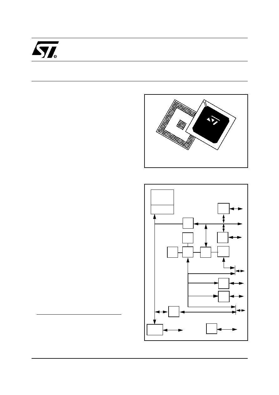
STPC� VEGA
X86 CORE PC COMPATIBLE SOC with ETHERNET and USB
PRELIMINARY DATA
PENTIUM
�
II CLASS PROCESSOR CORE
64-BIT SDRAM CONTROLLER RUNNING
AT UP TO 100 MHZ
PCI 2.1 COMPLIANT MASTER/SLAVE
CONTROLLER
ISA MASTER / SLAVE
DUAL PORT USB HOST CONTROLLER
(OHCI)
10/100 ETHERNET MAC
1)
INTEGRATED PERIPHERAL CONTROLLER
WITH SUPPPORT FOR EXTERNAL RTC
ULTRA DMA-66 IDE CONTROLLER
POWER MANAGEMENT UNIT
16-BIT LOCAL BUS INTERFACE
I2C BUS CONTROLLER
UART (1 RxTx)
IEEE 1149.1 JTAG INTERFACE
8 GENERAL PURPOSE IO
PROGRAMMABLE CLOCKS
0.18 MICRON TECHNOLOGY
1.8 V CORE & 3.3 V I/Os
LOW POWER CONSUMPTION DEVICE
DESCRIPTION
The STPC VEGA integrates a fully static Pentium
�
II
�
Class processor, fully compatible with Industry
Standards, and combines it with a powerful
chipset to provide a general purpose PC compati-
ble subsystem on a single device. The device is
packaged in a 388 Ball Grid Array (PBGA).
1- The usage of the internal MAC 10/100 is very
restricted. For more information see
10/100
Ethernet Controller description.
1
PBGA388
ST
PC
VE
GA
P-II� CLASS
CORE
HOST I/F
SDRAM
I/F
PCI
I/F
PCI
UIDE
ISA
I/F
PCI
I/F
ISA BUS
LB
I/F
LOCAL BUS
IPC
JTAG
PMU
GPIO
USB
10/100
MAC
I
2
C
ISA BUS
Block Diagram

Table of Contents
86
2/86
1 INTRODUCTION . . . . . . . . . . . . . . . . . . . . . . . . . . . . . . . . . . . . . . . . . . . . . . . . . . . . . . . . . . . . . . 6
1.1 MEMORY CONTROLLER . . . . . . . . . . . . . . . . . . . . . . . . . . . . . . . . . . . . . . . . . . . . . . . . . . 6
1.2 FEATURE MULTIPLEXING . . . . . . . . . . . . . . . . . . . . . . . . . . . . . . . . . . . . . . . . . . . . . . . . . 7
1.3 POWER MANAGEMENT . . . . . . . . . . . . . . . . . . . . . . . . . . . . . . . . . . . . . . . . . . . . . . . . . . . 7
1.4 JTAG . . . . . . . . . . . . . . . . . . . . . . . . . . . . . . . . . . . . . . . . . . . . . . . . . . . . . . . . . . . . . . . . . . 7
1.5 I2C . . . . . . . . . . . . . . . . . . . . . . . . . . . . . . . . . . . . . . . . . . . . . . . . . . . . . . . . . . . . . . . . . . . . 7
1.6 CLOCK TREE . . . . . . . . . . . . . . . . . . . . . . . . . . . . . . . . . . . . . . . . . . . . . . . . . . . . . . . . . . . 8
2 PIN DESCRIPTION . . . . . . . . . . . . . . . . . . . . . . . . . . . . . . . . . . . . . . . . . . . . . . . . . . . . . . . . . . . 11
2.1 INTRODUCTION . . . . . . . . . . . . . . . . . . . . . . . . . . . . . . . . . . . . . . . . . . . . . . . . . . . . . . . . 11
2.2 SIGNAL DESCRIPTIONS . . . . . . . . . . . . . . . . . . . . . . . . . . . . . . . . . . . . . . . . . . . . . . . . . 17
2.2.1
BASIC CLOCKS AND RESETS . . . . . . . . . . . . . . . . . . . . . . . . . . . . . . . . . . . . . . . 17
2.2.2
MEMORY INTERFACE . . . . . . . . . . . . . . . . . . . . . . . . . . . . . . . . . . . . . . . . . . . . . 17
2.2.3
PCI INTERFACE . . . . . . . . . . . . . . . . . . . . . . . . . . . . . . . . . . . . . . . . . . . . . . . . . . 17
2.2.4
ISA INTERFACE . . . . . . . . . . . . . . . . . . . . . . . . . . . . . . . . . . . . . . . . . . . . . . . . . . . 18
2.2.5
X-BUS INTERFACE . . . . . . . . . . . . . . . . . . . . . . . . . . . . . . . . . . . . . . . . . . . . . . . . 19
2.2.6
LOCAL BUS . . . . . . . . . . . . . . . . . . . . . . . . . . . . . . . . . . . . . . . . . . . . . . . . . . . . . . 20
2.2.7
IDE INTERFACE . . . . . . . . . . . . . . . . . . . . . . . . . . . . . . . . . . . . . . . . . . . . . . . . . . 20
2.2.8
USB Interface . . . . . . . . . . . . . . . . . . . . . . . . . . . . . . . . . . . . . . . . . . . . . . . . . . . . . 20
2.2.9
MEDIA ACCESS CONTROLLER (MAC) ETHERNET INTERFACE (LAN) . . . . . . 21
2.2.10 I2C . . . . . . . . . . . . . . . . . . . . . . . . . . . . . . . . . . . . . . . . . . . . . . . . . . . . . . . . . . . . . 21
2.2.11 JTAG Interface . . . . . . . . . . . . . . . . . . . . . . . . . . . . . . . . . . . . . . . . . . . . . . . . . . . . 21
2.2.12 MISCELLANEOUS . . . . . . . . . . . . . . . . . . . . . . . . . . . . . . . . . . . . . . . . . . . . . . . . . 21
2.3 SIGNAL DETAIL . . . . . . . . . . . . . . . . . . . . . . . . . . . . . . . . . . . . . . . . . . . . . . . . . . . . . . . . 23
3 STRAP OPTIONS . . . . . . . . . . . . . . . . . . . . . . . . . . . . . . . . . . . . . . . . . . . . . . . . . . . . . . . . . . . . 27
3.1 POWER ON STRAP REGISTER DESCRIPTIONS . . . . . . . . . . . . . . . . . . . . . . . . . . . . . . 28
3.1.1
ADPC Strap Register 0 Configuration . . . . . . . . . . . . . . . . . . . . . . . . . . . . . . . . . 28
3.1.2
ADPC Strap Register 1 Configuration . . . . . . . . . . . . . . . . . . . . . . . . . . . . . . . . . 29
3.1.3
ADPC Strap Register 2 Configuration . . . . . . . . . . . . . . . . . . . . . . . . . . . . . . . . . . 31
4 ELECTRICAL SPECIFICATIONS . . . . . . . . . . . . . . . . . . . . . . . . . . . . . . . . . . . . . . . . . . . . . . . . 32
4.1 INTRODUCTION . . . . . . . . . . . . . . . . . . . . . . . . . . . . . . . . . . . . . . . . . . . . . . . . . . . . . . . . 32
4.2 ELECTRICAL CONNECTIONS . . . . . . . . . . . . . . . . . . . . . . . . . . . . . . . . . . . . . . . . . . . . . 32
4.2.1
Power/Ground Connections/Decoupling . . . . . . . . . . . . . . . . . . . . . . . . . . . . . . . . . 32
4.2.2
Unused Input Pins . . . . . . . . . . . . . . . . . . . . . . . . . . . . . . . . . . . . . . . . . . . . . . . . . 32
4.2.3
Reserved Designated Pins . . . . . . . . . . . . . . . . . . . . . . . . . . . . . . . . . . . . . . . . . . . 32
4.3 ABSOLUTE MAXIMUM RATINGS . . . . . . . . . . . . . . . . . . . . . . . . . . . . . . . . . . . . . . . . . . . 32
4.4 DC CHARACTERISTICS . . . . . . . . . . . . . . . . . . . . . . . . . . . . . . . . . . . . . . . . . . . . . . . . 33
4.5 AC CHARACTERISTICS . . . . . . . . . . . . . . . . . . . . . . . . . . . . . . . . . . . . . . . . . . . . . . . . . . 34
4.5.1
Power on sequence . . . . . . . . . . . . . . . . . . . . . . . . . . . . . . . . . . . . . . . . . . . . . . . . 36
4.5.2
RESET sequence . . . . . . . . . . . . . . . . . . . . . . . . . . . . . . . . . . . . . . . . . . . . . . . . . . 37
4.5.3
SDRAM interface . . . . . . . . . . . . . . . . . . . . . . . . . . . . . . . . . . . . . . . . . . . . . . . . . . 38
4.5.4
PCI interface . . . . . . . . . . . . . . . . . . . . . . . . . . . . . . . . . . . . . . . . . . . . . . . . . . . . . . 39
4.5.5
IPC interface . . . . . . . . . . . . . . . . . . . . . . . . . . . . . . . . . . . . . . . . . . . . . . . . . . . . . . 40
4.5.6
Isa interface AC Timing characteristics . . . . . . . . . . . . . . . . . . . . . . . . . . . . . . . . . 41
4.5.7
Local bus interface . . . . . . . . . . . . . . . . . . . . . . . . . . . . . . . . . . . . . . . . . . . . . . . . . 46
4.5.8
USB interface . . . . . . . . . . . . . . . . . . . . . . . . . . . . . . . . . . . . . . . . . . . . . . . . . . . . . 49
4.5.9
JTAG interface . . . . . . . . . . . . . . . . . . . . . . . . . . . . . . . . . . . . . . . . . . . . . . . . . . . . 49
1

Table of Contents
3/86
4.5.10 i2C interface . . . . . . . . . . . . . . . . . . . . . . . . . . . . . . . . . . . . . . . . . . . . . . . . . . . . . . 50
5 MECHANICAL DATA . . . . . . . . . . . . . . . . . . . . . . . . . . . . . . . . . . . . . . . . . . . . . . . . . . . . . . . . . 51
5.1 388-PIN PACKAGE DIMENSIONS . . . . . . . . . . . . . . . . . . . . . . . . . . . . . . . . . . . . . . . . . . 51
5.2 388-PIN PACKAGE THERMAL DATA . . . . . . . . . . . . . . . . . . . . . . . . . . . . . . . . . . . . . . . . 54
5.3 SOLDERING RECOMMENDATIONS . . . . . . . . . . . . . . . . . . . . . . . . . . . . . . . . . . . . . . . . 56
6 DESIGN GUIDELINES . . . . . . . . . . . . . . . . . . . . . . . . . . . . . . . . . . . . . . . . . . . . . . . . . . . . . . . . 57
6.1 TYPICAL APPLICATIONS . . . . . . . . . . . . . . . . . . . . . . . . . . . . . . . . . . . . . . . . . . . . . . . . . 57
6.1.1
File Server . . . . . . . . . . . . . . . . . . . . . . . . . . . . . . . . . . . . . . . . . . . . . . . . . . . . . . . 57
6.1.2
Graphics Terminal . . . . . . . . . . . . . . . . . . . . . . . . . . . . . . . . . . . . . . . . . . . . . . . . . 57
6.2 STPC CONFIGURATION . . . . . . . . . . . . . . . . . . . . . . . . . . . . . . . . . . . . . . . . . . . . . . . . . . 58
6.2.1
Local Bus / ISA bus . . . . . . . . . . . . . . . . . . . . . . . . . . . . . . . . . . . . . . . . . . . . . . . . 58
6.2.2
Clock configuration . . . . . . . . . . . . . . . . . . . . . . . . . . . . . . . . . . . . . . . . . . . . . . . . . 58
6.3 ARCHITECTURE RECOMMENDATIONS . . . . . . . . . . . . . . . . . . . . . . . . . . . . . . . . . . . . . 58
6.3.1
POWER Decoupling . . . . . . . . . . . . . . . . . . . . . . . . . . . . . . . . . . . . . . . . . . . . . . . . 59
6.3.2
14MHz oscillator stage . . . . . . . . . . . . . . . . . . . . . . . . . . . . . . . . . . . . . . . . . . . . . . 59
6.3.3
SDRAM . . . . . . . . . . . . . . . . . . . . . . . . . . . . . . . . . . . . . . . . . . . . . . . . . . . . . . . . . . 60
6.3.4
PCI bus . . . . . . . . . . . . . . . . . . . . . . . . . . . . . . . . . . . . . . . . . . . . . . . . . . . . . . . . . . 62
6.3.5
Local Bus . . . . . . . . . . . . . . . . . . . . . . . . . . . . . . . . . . . . . . . . . . . . . . . . . . . . . . . . 64
6.3.6
IPC . . . . . . . . . . . . . . . . . . . . . . . . . . . . . . . . . . . . . . . . . . . . . . . . . . . . . . . . . . . . . 65
6.3.7
IDE / ISA dynamic demultiplexing . . . . . . . . . . . . . . . . . . . . . . . . . . . . . . . . . . . . . . 67
6.3.8
Basic audio using IDE interface . . . . . . . . . . . . . . . . . . . . . . . . . . . . . . . . . . . . . . . 67
6.3.9
USB interface . . . . . . . . . . . . . . . . . . . . . . . . . . . . . . . . . . . . . . . . . . . . . . . . . . . . . 68
6.3.10 JTAG interface . . . . . . . . . . . . . . . . . . . . . . . . . . . . . . . . . . . . . . . . . . . . . . . . . . . . 69
6.4 PLACE AND ROUTE RECOMMENDATIONS . . . . . . . . . . . . . . . . . . . . . . . . . . . . . . . . . . 70
6.4.1
General recommendations . . . . . . . . . . . . . . . . . . . . . . . . . . . . . . . . . . . . . . . . . . . 70
6.4.2
PLL Definition and Implementation . . . . . . . . . . . . . . . . . . . . . . . . . . . . . . . . . . . . . 70
6.4.3
Memory Interface . . . . . . . . . . . . . . . . . . . . . . . . . . . . . . . . . . . . . . . . . . . . . . . . . . 71
6.4.4
PCI Interface . . . . . . . . . . . . . . . . . . . . . . . . . . . . . . . . . . . . . . . . . . . . . . . . . . . . . . 74
6.5 THERMAL DISSIPATION . . . . . . . . . . . . . . . . . . . . . . . . . . . . . . . . . . . . . . . . . . . . . . . . . 76
6.6 DEBUG METHODOLOGY . . . . . . . . . . . . . . . . . . . . . . . . . . . . . . . . . . . . . . . . . . . . . . . . . 81
6.6.1
Power Supplies . . . . . . . . . . . . . . . . . . . . . . . . . . . . . . . . . . . . . . . . . . . . . . . . . . . . 81
6.6.2
Boot sequence . . . . . . . . . . . . . . . . . . . . . . . . . . . . . . . . . . . . . . . . . . . . . . . . . . . . 81
6.6.3
ISA mode . . . . . . . . . . . . . . . . . . . . . . . . . . . . . . . . . . . . . . . . . . . . . . . . . . . . . . . . 81
6.6.4
Local Bus mode . . . . . . . . . . . . . . . . . . . . . . . . . . . . . . . . . . . . . . . . . . . . . . . . . . . 82
6.6.5
Summary . . . . . . . . . . . . . . . . . . . . . . . . . . . . . . . . . . . . . . . . . . . . . . . . . . . . . . . . 83
7 ORDERING INFORMATION . . . . . . . . . . . . . . . . . . . . . . . . . . . . . . . . . . . . . . . . . . . . . . . . . . . . 85
7.1 ORDERING INFORMATION SCHEME . . . . . . . . . . . . . . . . . . . . . . . . . . . . . . . . . . . . . . . 85
7.2 ORDER CODES . . . . . . . . . . . . . . . . . . . . . . . . . . . . . . . . . . . . . . . . . . . . . . . . . . . . . . . . 85
7.3 CUSTOMER SERVICE . . . . . . . . . . . . . . . . . . . . . . . . . . . . . . . . . . . . . . . . . . . . . . . . . . . 85
8 REVISION HISTORY . . . . . . . . . . . . . . . . . . . . . . . . . . . . . . . . . . . . . . . . . . . . . . . . . . . . . . . . . . 86

STPC� VEGA
4/86
X86 Processor
x86 Pentium� II class processor running in
X2 mode
-3 Issue integer six-stage pipeline/clock
-3 issue MMX�/clock
-Pipelined FPU
Bus clock with skew correction
Internal core clocks generated as multiples of
bus clock with multiplication factors of X2,
X2.5, X3, X3.5
SDRAM Interface
64-bit data bus
100 MHz maximum SDRAM clock
8 MByte to 256 MByte memory size (only the
upper 128MByte cacheable)
Supports 16 Mbit to 256 Mbit memories
Support for -8 to -15 memory parts
Supports buffered and non-buffered DIMMs
Supports registered DIMMs
Programmable latency
PCI Controller Master/Slave
Compatible with PCI Version 2.1 specification
Integrated PCI arbitration interface. Up to
three external masters can be directly
connected
Master/Slave Bridge to USB, LAN, UIDE &
ISA cycles
Support for burst read/write from PCI master
0.20X, 0.25X, 0.33X and 0.5X Host clock PCI
clock. Automatically selected.
ISA Master/Slave
Generates the ISA clock from either
14.318 MHz oscillator clock or PCI clock
Supports programmable extra wait state for
ISA cycles
Supports I/O recovery time for back to back
I/O cycles
Fast Gate A20 and Fast reset
Supports Flash ROM
Supports ISA hidden refresh
Buffered DMA and ISA master cycles to
reduce the bandwidth utilization of PCI and
system bus
Local Bus
Multiplexed with ISA interface
16-bit bus data path with word steering
capability
Two cacheable banks of 32 Mbyte flash
devices (boot block shadowed from
000C0000h to 000FFFFFh)
Programmable timing with host clock
granularity for flash accesses
32-bit flash burst support
Two-level hardware key protection for flash
boot block protection
Up to eight IO devices (four Chipselects)
supported with programmable start address
& size
IO device timing (setup & recovery time)
programmable
Integrated Peripherals Controller
Interrupt Controller: 8259 compatible (two
Interrupt controllers)
DMA Controller: 8237 compatible (two DMA
controllers)
Page register
Counter 0 and counter 1 gates are always on,
counter 2 is controlled by writing to Port B
Supports external RTC
Ultra DMA-66 IDE Controller
Supports IDE hard drives larger than
528 MBytes
Support for two connectors to allow up to four
drives
Support for CD-ROM and tape peripherals
Support for 11.1/16.6 Mbytes/second, I/O
Channel Ready PIO data transfers
Supports up to 66 Mbytes/second, UDMA
data transfers
Ultra DMA supports CRC-16 error checking
protocol (no correction supported)
PIO: 0 to 5, DMA: 0 to 2, UDMA: 0 to 4
Backward compatibility with IDE (ATA-1)
8 GPIO
Individual pins programmable as either input
or output
Interrupt generation with selectable masking
1

STPC� VEGA
5/86
10/100 Ethernet Controller
The usage of VEGA internal MAC is very restricted
and tested only under Linux operating system with
the specific configuration 100Mb/s Half and Full
Duplex . Any other functional configuration is not
guaranteed by STMicroelectronics.
Problem that maybe occur is a file transfer
corruption , however the use of the internal MAC
for browsing applications or http session does not
causes problem.
Compliant with IEEE 802.3, 802.3u
specification
Supports 10/100 Mb/s data transfer rates
IEEE 802.3 compliant MII interface to talk to
an external physical layer (PHY)
VLAN support
Supports both full-duplex and half-duplex
operations
Supports CSMA/CD Protocol for half-duplex
Supports flow-control for full-duplex operation
Collision detection and auto retransmission
on collisions in half-duplex mode
Management support using a variety of
counters
Preamble generation and removal
Automatic 32-bit CRC generation and
checking
Optional insertion of PAD/CRC32 on transmit
Options for Automatic Pad stripping on the
receive packets
Provides external and internal loop back
capability on the MII Interface
Contains a variety of flexible address filtering
modes on the Ethernet side:
- One 48-bit Perfect address
- 64 hash-filtered multicast addresses
- Pass all multicast addresses
- Promiscuous Mode
- Pass all incoming packets with a status
report
USB Host Controller
Open HCI Rev 1.1 compatible
USB Rev 1.1 compatible
Root hub with two down-stream ports with
power switching control
Support of both low & high speed USB
devices
Support of system management interupt
(SMI)
UART
One UART RxTx only
Programmable word length, stop bits and
parity
Programmable baud rate generator
Interrupt generator
Loop-back mode
Scratch register
Two 16-byte FIFOs
Power Management Unit
Four power saving modes: On, Doze,
Standby, Suspend
Programmable system activity detector
Supports STPCLK#
I2C Bus Controller
One I2C compliant master/slave bus
controller
Slow and fast modes supported
JTAG Function
Boundary Scan Chain function
1