 | ÐлекÑÑоннÑй компоненÑ: STPR620CF | СкаÑаÑÑ:  PDF PDF  ZIP ZIP |
Äîêóìåíòàöèÿ è îïèñàíèÿ www.docs.chipfind.ru

1/7
STPR620CT/CF/CFP
®
January 2002- Ed:3D
ULTRA FAST RECOVERY RECTIFIER DIODES
ISOWATT220AB
STPR620CF
s
Suited for SMPS
s
Low losses
s
Low forward and reverse recovery time
s
High surge current capability
s
Insulated packages:
ISOWATT220AB / TO-220FPAB
Insulation voltage = 2000V DC
Capacitance = 12pF
FEATURES
Symbol
Parameter
Value
Unit
V
RRM
Repetitive peak reverse voltage
200
V
I
F(RMS)
RMS forward current
Per diode
10
A
I
F(AV)
Average forward
current
= 0.5
TO-220AB
Tc=125°C
Per diode
3
A
ISOWATT220AB
TO-220FPAB
Tc=120°C Per device
6
I
FSM
Surge non repetitive forward current
tp=10ms sinusoidal
30
A
T
stg
Storage temperature range
- 65 to + 150
°C
Tj
Maximum junction temperature
150
°C
ABSOLUTE MAXIMUM (limiting values)
K
A1
A2
A1
K
A2
TO-220AB
STPR620CT
K
A1
A2
Low cost dual center tap rectifier suited for
Switched Mode Power Supplies and high fre-
quency DC to DC converters.
Packaged
in
TO-220AB,
TO-220FPAB
and
ISOWATT220AB, this device is intended for use
in low voltage, high frequency inverters, free
wheeling and polarity protection applications.
DESCRIPTION
A1
A2
K
TO-220FPAB
STPR620CFP
I
F(AV)
2 x 3 A
V
RRM
200 V
T
j(max)
150°C
V
F(max
)
0.99 V
t
rr(max)
30 ns
MAIN PRODUCT CHARACTERISTICS
STPR620CT/CF/CFP
2/7
Symbol
Test Conditions
Min.
Typ.
Max.
Unit
I
R
*
T
j
= 25°C
V
R
= V
RRM
50
µ
A
T
j
= 100°C
0.6
mA
V
F **
T
j
= 125
°
C
I
F
= 3 A
0.99
V
T
j
= 125
°
C
I
F
= 6 A
1.20
T
j
= 25
°
C
I
F
= 6 A
1.25
Pulse test :
* tp = 5 ms,
< 2 %
** tp = 380
µ
s,
< 2 %
ELECTRICAL CHARACTERISTICS
STATIC CHARACTERISTICS
Symbol
Test Conditions
Min.
Typ.
Max.
Unit
trr
T
j
= 25°C
I
F
= 0.5A
I
R
= 1A
Irr = 0.25A
30
ns
tfr
T
j
= 25
°
C
I
F
= 1A
V
FR
= 1.1 x V
F
tr = 10 ns
20
ns
V
FP
T
j
= 25
°
C
I
F
= 1A
tr = 10 ns
3
V
To evaluate the conduction losses use the following equation :
P = 0.78 x I
F(AV)
+ 0.070 x I
F
2
(RMS)
RECOVERY CHARACTERISTICS
Symbol
Parameter
Value
Unit
R
th (j-c)
Junction to case
TO-220AB
Per diode
6.5
°
C/W
ISOWATT220AB
TO-220FPAB
Per diode
8.5
When the diodes 1 and 2 are used simultaneously :
Tj(diode 1) = P(diode 1) x Rth(j-c) (Per diode) + P(diode 2) x Rth(c)
THERMAL RESISTANCES
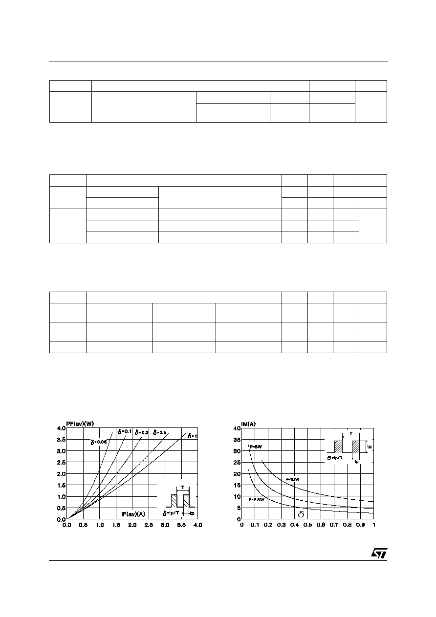
Fig. 2: Peak current versus form factor (Per diode).
Fig. 1: Average forward power dissipation versus
average forward current (Per diode).
STPR620CT/CF/CFP
3/7
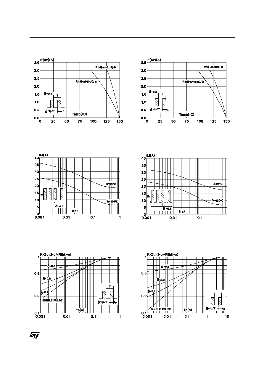
Fig. 3: Average current versus ambient tempera-
ture.(duty cycle: 0.5) (TO-220AB)
Fig. 5: Non repetitive surge peak forward current
versus overload duration (Maximum values) (Per di-
ode) (TO-220AB).
Fig. 7: Relative variation of thermal transient im-
pedance junction to case versus pulse duration
(Per diode) (TO-220AB).
Fig. 4: Average current versus ambient temperature.
(duty cycle : 0.5) (ISOWATT220AB / TO-220FPAB)
Fig. 6: Non repetitive surge peak forward current
versus overload duration (Maximum values) (Per
diode) (ISOWATT220AB / TO-220FPAB).
Fig. 8: Relative variation of thermal transient im-
pedance junction to case versus pulse duration
(Per diode) (ISOWATT220AB / TO-220FPAB).
STPR620CT/CF/CFP
4/7
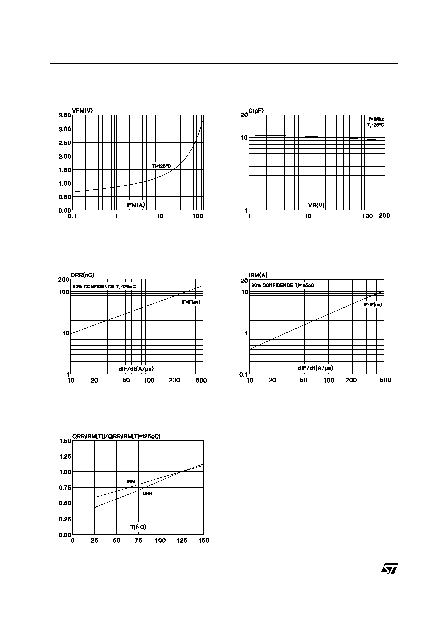
Fig. 10: Junction capacitance versus reverse
voltage applied (Typical values) (Per diode).
Fig. 11: Recovery charges versus dI
F
/dt (Per
diode).
Fig. 13: Dynamic parameters versus junction
temperature (Per diode).
Fig. 12: Peak reverse current versus dIF/dt (Per
diode).
Fig. 9: Forward voltage drop versus forward
current. (Maximum values) (Per diode).
STPR620CT/CF/CFP
5/7
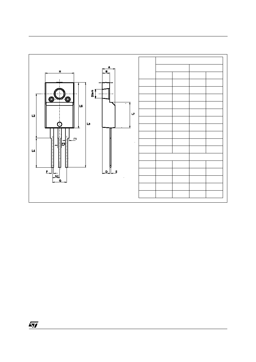
PACKAGE MECHANICAL DATA
ISOWATT220AB (JEDEC outline)
REF.
DIMENSIONS
Millimeters
Inches
Min.
Max.
Min.
Max.
A
4.40
4.60
0.173
0.181
B
2.50
2.70
0.098
0.106
D
2.50
2.75
0.098
0.108
E
0.40
0.70
0.016
0.028
F
0.75
1.00
0.030
0.039
F1
1.15
1.70
0.045
0.067
F2
1.15
1.70
0.045
0.067
G
4.95
5.20
0.195
0.205
G1
2.40
2.70
0.094
0.106
H
10.00
10.40
0.394
0.409
L2
16.00 typ.
0.630 typ.
L3
28.60
30.60
1.125
1.205
L4
9.80
10.60
0.386
0.417
L6
15.90
16.40
0.626
0.646
L7
9.00
9.30
0.354
0.366
Diam
3.00
3.20
0.118
0.126