Äîêóìåíòàöèÿ è îïèñàíèÿ www.docs.chipfind.ru
Rev 2
October 2005
1/31
1
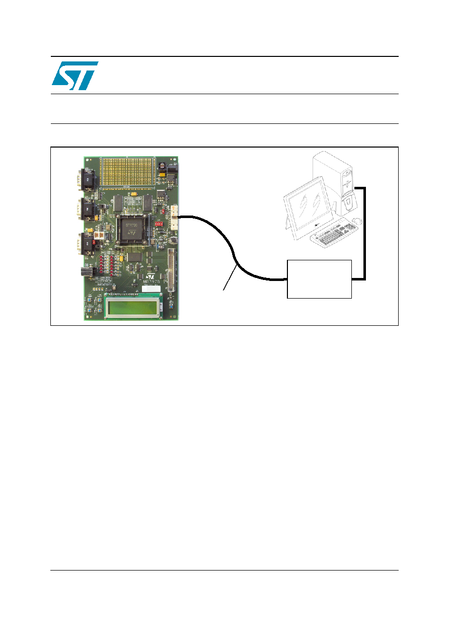
STR720-EVAL
Evaluation Board for STR72xF
Main components
STR720 processor running at 66 MHz
EMI flash 4 Mbytes (2M x 16)
SMI SDRAM 16 Mbytes (2 x (4M x 16))
SPI serial flash
LCD display
Features
Support for the following interfaces:
ATAPI
USB
CAN
RS232
LED displays
Test buttons
JTAG connector
Description
The STR720-EVAL board is a complete
development platform for the STR720 series. It is
a cost effective, flexible and open design to
demonstrate the capability of the STR720 series
of microcontrollers and enable rapid evaluation of
the STR720 devices and peripherals. It uses the
high performance STR720 ARM720T
TM
device
that embeds 8 Kbytes unified cache, has a
memory management unit (MMU), 16K program
RAM and numerous peripheral interfaces,
including USB and CAN.
The STR720-EVAL board includes shared
memory interface (SMI) SDRAM and flash
memory on the external memory interface (EMI)
to enable freedom in development of large
programs before custom hardware is designed. It
integrates a 2 x 16 LCD, LEDs, UART, CAN, USB
interfaces and test buttons to create a versatile
stand-alone test platform. A wide choice of third
party development tools are available in addition
to those available from STMicroelectronics.
Host to JTAG
interface
High speed JTAG
debug port
connection
STR720-EVAL
board
www.st.com

STR720-EVAL
1/31
1
Introduction . . . . . . . . . . . . . . . . . . . . . . . . . . . . . . . . . . . . . . . . . . . . . . . . . . 3
1.1
Processor and memory devices on this board . . . . . . . . . . . . . . . . . . . . . . . . 3
1.2
Board interface connections . . . . . . . . . . . . . . . . . . . . . . . . . . . . . . . . . . . . . . 4
1.3
Push buttons . . . . . . . . . . . . . . . . . . . . . . . . . . . . . . . . . . . . . . . . . . . . . . . . . . 4
1.4
Displays . . . . . . . . . . . . . . . . . . . . . . . . . . . . . . . . . . . . . . . . . . . . . . . . . . . . . 4
2
Hardware . . . . . . . . . . . . . . . . . . . . . . . . . . . . . . . . . . . . . . . . . . . . . . . . . . . . 5
2.1
Overview . . . . . . . . . . . . . . . . . . . . . . . . . . . . . . . . . . . . . . . . . . . . . . . . . . . . . 7
2.2
Processor . . . . . . . . . . . . . . . . . . . . . . . . . . . . . . . . . . . . . . . . . . . . . . . . . . . . 7
2.3
Debug . . . . . . . . . . . . . . . . . . . . . . . . . . . . . . . . . . . . . . . . . . . . . . . . . . . . . . . 7
2.4
Prototype area . . . . . . . . . . . . . . . . . . . . . . . . . . . . . . . . . . . . . . . . . . . . . . . . 7
2.5
Reset . . . . . . . . . . . . . . . . . . . . . . . . . . . . . . . . . . . . . . . . . . . . . . . . . . . . . . . . 7
2.6
Memory . . . . . . . . . . . . . . . . . . . . . . . . . . . . . . . . . . . . . . . . . . . . . . . . . . . . . . 7
2.7
Power supplies . . . . . . . . . . . . . . . . . . . . . . . . . . . . . . . . . . . . . . . . . . . . . . . . 8
2.8
USB full speed interface . . . . . . . . . . . . . . . . . . . . . . . . . . . . . . . . . . . . . . . . . 8
2.9
CAN interface . . . . . . . . . . . . . . . . . . . . . . . . . . . . . . . . . . . . . . . . . . . . . . . . . 8
2.10
RS232 serial interfaces . . . . . . . . . . . . . . . . . . . . . . . . . . . . . . . . . . . . . . . . . . 8
2.11
Analog input . . . . . . . . . . . . . . . . . . . . . . . . . . . . . . . . . . . . . . . . . . . . . . . . . . 8
2.12
LEDs . . . . . . . . . . . . . . . . . . . . . . . . . . . . . . . . . . . . . . . . . . . . . . . . . . . . . . . . 9
2.13
Push buttons . . . . . . . . . . . . . . . . . . . . . . . . . . . . . . . . . . . . . . . . . . . . . . . . . 10
2.14
Option jumper placement . . . . . . . . . . . . . . . . . . . . . . . . . . . . . . . . . . . . . . . 10
2.15
Option switch settings . . . . . . . . . . . . . . . . . . . . . . . . . . . . . . . . . . . . . . . . . . 12
3
Connectors . . . . . . . . . . . . . . . . . . . . . . . . . . . . . . . . . . . . . . . . . . . . . . . . . . 14
3.1
USB . . . . . . . . . . . . . . . . . . . . . . . . . . . . . . . . . . . . . . . . . . . . . . . . . . . . . . . . 14
3.2
CAN bus connector . . . . . . . . . . . . . . . . . . . . . . . . . . . . . . . . . . . . . . . . . . . . 14
3.3
RS232 serial data connector . . . . . . . . . . . . . . . . . . . . . . . . . . . . . . . . . . . . . 15
3.4
Debug . . . . . . . . . . . . . . . . . . . . . . . . . . . . . . . . . . . . . . . . . . . . . . . . . . . . . . 15
3.5
ATAPI interface . . . . . . . . . . . . . . . . . . . . . . . . . . . . . . . . . . . . . . . . . . . . . . . 16
3.6
ADC input . . . . . . . . . . . . . . . . . . . . . . . . . . . . . . . . . . . . . . . . . . . . . . . . . . . 17
4
Schematics . . . . . . . . . . . . . . . . . . . . . . . . . . . . . . . . . . . . . . . . . . . . . . . . . . 18
4.1
STR720-EVAL board top sheet 1 of 2 . . . . . . . . . . . . . . . . . . . . . . . . . . . . . 18
4.2
STR720-EVAL board top sheet 2 of 2 . . . . . . . . . . . . . . . . . . . . . . . . . . . . . 19

STR720-EVAL
2/31
4.3
STR720-Eval board - SMI SDRAM . . . . . . . . . . . . . . . . . . . . . . . . . . . . . . . 20
4.4
STR720-Eval board - EMI . . . . . . . . . . . . . . . . . . . . . . . . . . . . . . . . . . . . . . 21
4.5
STR720-Eval board - EMI ATAPI interface . . . . . . . . . . . . . . . . . . . . . . . . . 22
4.6
STR720-Eval board - EMI flash . . . . . . . . . . . . . . . . . . . . . . . . . . . . . . . . . . 23
4.7
STR720-Eval board - EMI LCD . . . . . . . . . . . . . . . . . . . . . . . . . . . . . . . . . . . 24
4.8
STR720-Eval board - ARM JTAG interface . . . . . . . . . . . . . . . . . . . . . . . . . 25
4.9
STR720-Eval board - USB interface . . . . . . . . . . . . . . . . . . . . . . . . . . . . . . . 26
4.10
STR720-Eval board - CAN interface . . . . . . . . . . . . . . . . . . . . . . . . . . . . . . 27
4.11
STR720-Eval board - serial flash interfaces . . . . . . . . . . . . . . . . . . . . . . . . . 28
4.12
STR720-Eval board - RS232 interface . . . . . . . . . . . . . . . . . . . . . . . . . . . . . 29
5
Revision history . . . . . . . . . . . . . . . . . . . . . . . . . . . . . . . . . . . . . . . . . . . . . . 30

1 Introduction
STR720-EVAL
3/31
1 Introduction
STMicroelectronics is a global independent semiconductor company that designs, develops,
manufactures and markets a broad range of semiconductor integrated circuits and discrete
devices used in a wide variety of applications.
The STR720-EVAL board is based on the STR720, a highly integrated microcontroller, running
at 66 MHz. It combines the popular ARM720T
TM
32-bit RISC CPU that embeds 8 Kbytes of
unified cache and a memory management unit (MMU) with16 Kbytes of program RAM, external
SDRAM interface for up to 128 Mbytes of SDRAM, an EMI for up to 8 Mbytes of SRAM, flash or
ROM and numerous on-chip peripherals.
This board is intended as a low cost development platform to demonstrate the capability of the
STR720 series of micro-controllers and to enable rapid evaluation of the STR720 devices and
available peripherals.
The STR720-EVAL board has 4 Mbytes of flash on EMI, 1-Mbit SPI serial flash and 16 Mbytes
of SDRAM. It supports ATAPI, USB, CAN and RS232 interfaces. The on-board chip
STR720RBQ6 is an ARM720T
TM
32-bit RISC micro-controller with cache and MMU.
This board includes a 2x16 programmable LCD display supported by reset, RTC reset, next,
select and previous push buttons.
The hardware platform of the STR720 series is supported by an extensive software support
package, including device drivers in ANSI C source form and demonstration software. It is
flashed with a demonstration application that shows the basic features of the device.
Development tools are readily available. This is complemented by a range of third party real-
time OS and middleware.
Design schematics can also be supplied in electronic format to those customers with
compatible design environments.
Note:
ARM
®
and ARM7TDMI
TM
are registered trademarks of ARM Limited in the EU and other
countries.
1.1
Processor and memory devices on this board
STR720 ARM720T
TM
processor running at 66 MHz, IC9:
208-pin PQFP version,
8 Kbytes cache,
16 Kbytes program RAM,
memory management unit (MMU),
dual voltage, 1.8 V for core supply and 3.3 V for inputs/outputs,
nested interrupt controller.
External memory interface:
flash (bank 0) 4 Mbytes arranged as 2M x 16: IC17,
LCD (bank 0), see
Section 1.4 on page 4
: LCD1,
ATAPI interface: CN3
SMI (bank 0) 16 Mbytes SDRAM arranged as (2 x (4M x 16)): IC8, IC15,

STR720-EVAL
1 Introduction
4/31
Clocking:
+3.3 V surface mounted 16 MHz oscillator provides the main clock source,
RTC real-time clock with embedded 32 KHz oscillator.
Serial ROM. A 1-Mbit SPI serial flash connected to the buffered serial peripheral interface
(BSPI): IC20.
1.2 Board
interface
connections
Diagrams and wiring descriptions for these connectors are provided in
Section 4 on page 18
.
The following connections are supported by the board:
USB support USB device using a type B connector: CN8,
CAN uses a single 9 D-type connector with microswitch selectable low or high speed
transceiver: CN7,
UART1 (Rx and Tx only) connected to a 9-way male D-type RS232 connector: CN5,
UART2 (Rx and Tx only) connected to a 9-way male D-type RS232 connector: CN6,
JTAG, 20 pin IDC connector: CN2,
variable resistor voltage range 0 to 2.5 V: VR1,
LM35 temperature sensor: IC4,
prototype area: GD1,
test points various test points are located throughout the board, for details see
Section 4.1
on page 18
,
main power supply: CN1.
1.3 Push
buttons
The following push buttons are provided, they are described further in
Section 2.13 on page 10
:
reset (RST), board reset: SW1,
previous (PRV), programmable switch: SW8,
next (NXT), programmable switch: SW9,
select (SEL), programmable switch: SW10,
RTC reset (RTCRST): SW11.
1.4 Displays
The following LCD and LEDs are provided:
LCD write-only display, 2x16 LCD display connected to the EMI using a buffer and address
decode logic, green back light display: LCD1,
surface mount red +5 V and +3.3 V power indicators: LD1, LD2,
surface mount yellow, IDE ATAPI +3.3 V power indicator: LD3,
surface mount yellow, USB connection indicator: LD18,
bi-color red/green, reset indicator: LD4,
low consumption LEDs red: LD5, LD6, LD7, LD8, LD9, LD10, LD11, LD12, LD13, LD14,
LD15, LD16, LD17.
Document Outline