 | –≠–ª–µ–∫—Ç—Ä–æ–Ω–Ω—ã–π –∫–æ–º–ø–æ–Ω–µ–Ω—Ç: STTA206S | –°–∫–∞—á–∞—Ç—å:  PDF PDF  ZIP ZIP |
TM : TURBOSWITCH is a trademark of STMicroelectronics
November 1999 - Ed: 2D
SPECIFIC TO "FREEWHEEL MODE" OPERA-
TIONS : FREEWHEEL OR BOOSTER DIODE
ULTRA-FAST AND SOFT RECOVERY
VERY LOW OVERALL POWER LOSSES IN
BOTH THE DIODE AND THE COMPANION
TRANSISTOR
HIGH FREQUENCY OPERATIONS
SURFACE MOUNT DEVICE
FEATURES AND BENEFITS
The TURBOSWITCH is a very high performance
series of ultra-fast high voltage power diodes from
600V to 1200V.
TURBOSWITCH "A" family drastically cuts losses
in both the diode and the associated switching
IGBT or MOSFET in all "Freewheel Mode"
operations and is particulary suitable and efficient
in Motor Control Freewheel applications and in
Booster diode applications in Power Factor Control
circuitries.
Packaged in SMC surface mount envelope, these
600V devices are particularly intended for use on
240V domestic mains.
DESCRIPTION
I
F(AV)
2A
V
RRM
600V
t
rr
(typ)
20ns
V
F
(max)
1.5V
MAIN PRODUCTS CHARACTERISTICS
Symbol
Parameter
Value
Unit
V
RRM
Repetitive peak reverse voltage
600
V
V
RSM
Non repetitive peak reverse voltage
600
V
I
F(RMS)
RMS forward current
8
A
I
FRM
Repetitive peak forward current (tp = 5
µ
s, f = 5kHz)
50
A
T
j
Maximum operating junction temperature
125
∞C
T
stg
Storage temperature range
- 65 to + 150
∞C
ABSOLUTE MAXIMUM RATINGS
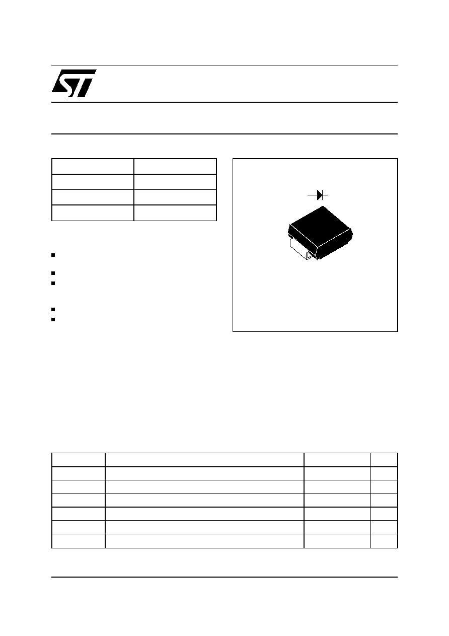
STTA206S
Æ
TURBOSWITCH
TM
"A". ULTRA-FAST HIGH VOLTAGE DIODE
A
K
SMC
1/8

Symbol
Parameter
Test Conditions
Min
Typ
Max
Unit
V
F *
Forward voltage drop
I
F
= 2A
Tj = 25∞C
Tj = 125∞C
1.1
1.75
1.5
V
I
R **
Reverse leakage current
V
R
= 0.8
x V
RRM
Tj = 25∞C
Tj = 125∞C
400
20
1200
µ
A
STATIC ELECTRICAL CHARACTERISTICS (see Fig. 2)
Symbol
Parameter
Conditions
Value
Unit
R
th(j-I)
Junction to lead
21
∞C/W
P
1
Conduction power dissipation
(see fig. 2)
I
F(AV)
= 1.5A
= 0.5
Tlead= 72∞C
2.5
W
P
max
Total power dissipation
Pmax = P1 + P3 (P3 = 10% P1)
Tlead= 67∞C
2.8
W
THERMAL AND POWER DATA
Symbol
Parameter
Test Conditions
Min
Typ
Max
Unit
t
rr
Reverse
recovery time
Tj = 25∞C
I
F
= 0.5 A I
R
= 1A Irr = 0.25A
I
F
= 1 A dI
F
/dt =-50A/
µ
s V
R
= 30V
20
50
ns
I
RM
Maximum
recovery current
Tj = 125∞C VR = 400V I
F
= 2A
dI
F
/dt = -16 A/
µ
s
dI
F
/dt = -50 A/
µ
s
2.0
1.2
A
S factor
Softness factor
Tj = 125∞C V
R
= 400V I
F
= 2A
dI
F
/dt = -50 A/
µ
s
TBD
-
DYNAMIC ELECTRICAL CHARACTERISTICS
TURN-OFF SWITCHING (see Fig. 3)
Symbol
Parameter
Test Conditions
Min
Typ
Max
Unit
t
fr
Forward
recovery time
Tj = 25∞C
I
F
= 1 A
dI
F
/dt = 8 A/
µ
s
measured at, 1.1
◊
V
F
max
500
ns
V
Fp
Peak forward
voltage
10
V
TURN-ON SWITCHING (see Fig.8)
Test pulses widths : * tp = 380
µ
s, duty cycle < 2%
** tp = 5 ms , duty cycle < 2%
STTA206S
2/8
TOTAL LOSSES
due to the diode
P = P1+ P2+ P3+ P4+ P5 Watts
SWITCHING
LOSSES
in the diode
OFF : P3 Watts
ON : P4 Watts
(Fig. 3 & 4)
CONDUCTION
LOSSES
in the diode
P1 Watts
(Fig. 2)
SWITCHING
LOSSES
in the transistor
due to the diode
P2 Watts
(Fig. 3)
REVERSE
LOSSES
in the diode
P2 Watts
(Fig. 2)
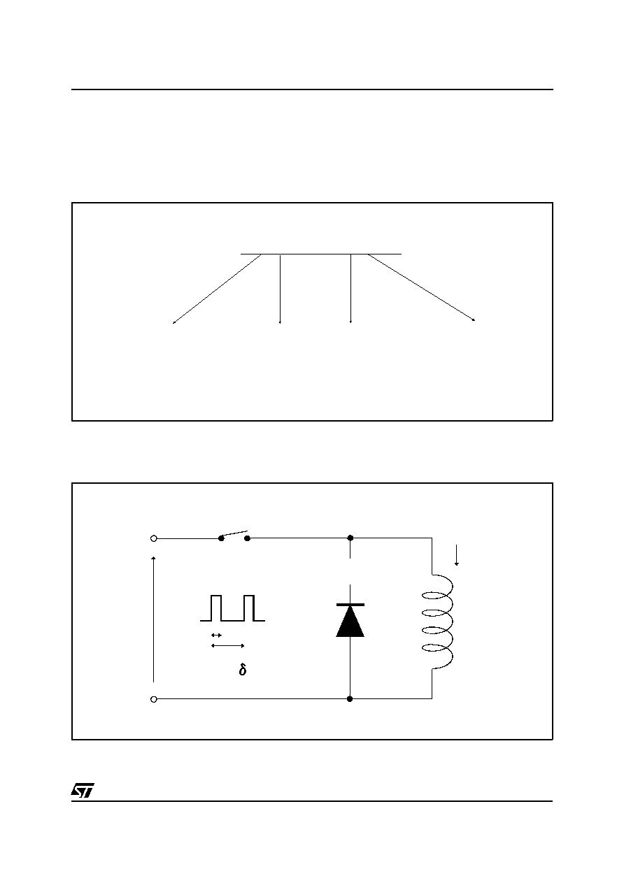
The TURBOSWITCH
TM
"A" is especially
designed to provide the lowest overall power
losses in any "Freewheel Mode" application (see
fig. 1) considering both the diode and the
companion transistor, thus optimizing the overall
performance in the end application.
The way of calculating the power losses is given
below :
APPLICATION DATA
DIODE:
TURBOSWITCH "A"
IL
LOAD
TRANSISTOR
SWITCHING
t
T
F = 1/T
= t/T
VR
Fig. 1 : "FREEWHEEL" MODE
STTA206S
3/8
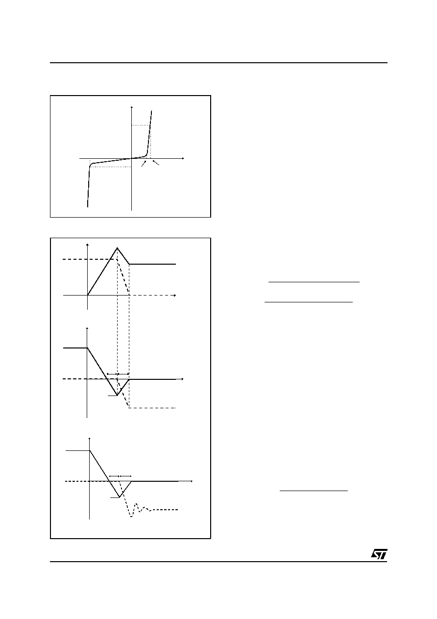
I
I F
Rd
I R
V R
VtO
V F
V
Fig. 2 : STATIC CHARACTERISTICS
Conduction losses :
P1 = V
t0
x I
F(AV)
+ R
d
x I
F
2
(RMS)
with
V
t0
= 1.15 V
R
d
= 0.175 Ohm
(Max values at 125∞C)
Reverse losses :
P2 = V
R
x I
R x (1 -
)
APPLICATION DATA (Cont'd)
Turn-on losses :
(in the transistor, due to the diode)
P5 =
V
R
◊
I
RM
2
◊
(
3
+
2
◊
S
)
◊
F
6
x
dI
F
/
dt
+
V
R
◊
I
RM
◊
I
L
◊
(
S
+
2
)
◊
F
2
◊
dI
F
/
dt
Turn-off losses (in the diode) :
P3 =
V
R
◊
I
RM
2
◊
S
◊
F
6
x dI
F
/
dt
P3 and P5 are suitable for power MOSFET and
IGBT
Fig. 3 : TURN-OFF CHARACTERISTICS
dI
F
/dt = V
R
/L
dI /dt
R
tb
ta
I
RM
V
R
I
V
t
S = tb/ta
trr = ta + tb
RECTIFIER
OPERATION
V
I
IL
t
TRANSISTOR
dI /dt
F
dI /dt
R
tb
ta
I RM
VR
DIODE
I
V
t
trr = ta + tb
S = tb / ta
STTA206S
4/8
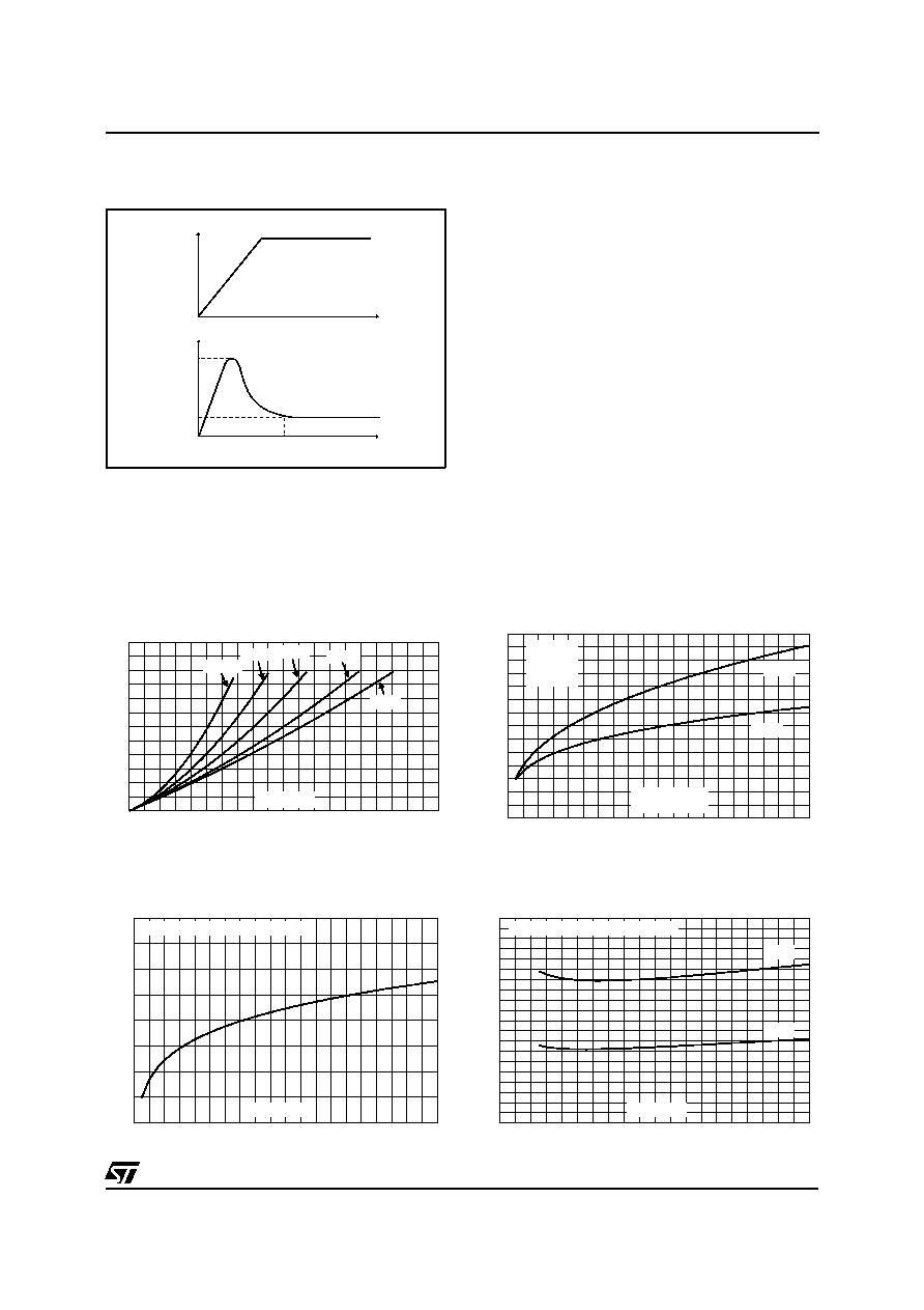
APPLICATION DATA (Cont'd)
I F
V F
V Fp
1.1V F
V F
F
dI /dt
0
0
t
t
I Fmax
tfr
Fig. 4 : TURN-ON CHARACTERISTICS
Turn-on losses :
P4
= 0.4 (V
FP
- V
F
) x I
Fmax
x t
fr
x F
Ratings and characteristics curves are ON
GOING.
0.0
0.2
0.4
0.6
0.8
1.0
1.2
1.4
1.6
1.8
2.0
0.0
0.5
1.0
1.5
2.0
2.5
3.0
P1(W)
IF(av) (A)
= 0.2
= 0.5
= 1
= 0.05
= 0.1
Fig. 5: Conduction losses versus average current.
0
20
40
60
80
100 120 140 160 180 200
0.00
0.05
0.10
0.15
0.20
0.25
0.30
0.35
P3(W)
Tj=125∞C
F=20KHz
VR=400V
IL=2A
IL=4A
dIF/dt(A/us)
Fig. 6: Switching OFF losses versus dIF/dt.
0
20
40
60
80
100
120
140
160
180
200
0
0.05
0.1
0.15
0.2
dIF/dt(A/us)
P4(W)
Tj=125∞C F=100KHz IF=IF(AV)
Fig. 7: Switching ON losses versus dIF/dt.
0
20
40
60
80
100
120
140
160
180
200
0.0
0.5
1.0
1.5
2.0
2.5
3.0
3.5
4.0
4.5
5.0
Tj=125∞C F=20KHz
VR=400V
IL=2A
IL=4A
P5(W)
dIF/dt(A/us)
Fig. 8: Switching losses in transistor due to the diode.
STTA206S
5/8