Æ
1/8
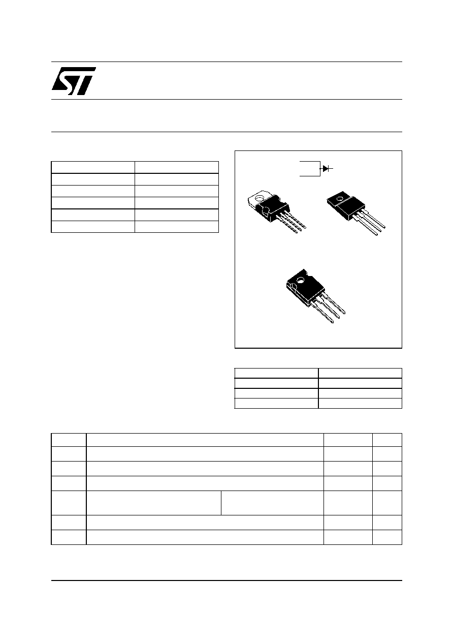
STTH40P03S
ULTRAFAST RECTIFIER PDP ENERGY RECOVERY
Table 3: Absolute Ratings (limiting values)
Symbol
Parameter
Value
Unit
V
RRM
Repetitive peak reverse voltage
300
V
I
F(RMS)
RMS forward voltage
80
A
I
F(AV)
Average forward current
40
A
I
FRM
Repetitive peak forward current
F = 200kHz, t
p
= 500ns
Sinusoidal waveform
120
A
T
stg
Storage temperature range
-65 to + 175
∞C
T
j
Maximum operating junction temperature
175
∞C
K
A
A
TO-220AB
STTH40P03ST
K
A
A
K
A
A
K
A
A
TO-220FPAB
STTH40P03SFP
TO-247
STTH40P03SW
July 2005
REV. 1
Table 1: Main Product Characteristics
FEATURES AND BENEFITS
Ultrafast recovery allowing High Sustain
Frequency
Decrease charge evacuation time (t
clamp
) in the
inductance (see figures 1 and 2)
Minimize switching-on and total power losses
Increase luminuous efficiency and brightness
Soft and noise-free recovery
High surge capability
High junction temperature
DESCRIPTION
The STTH40P03S is an Ultrafast Recovery Power
Rectifier dedicated to energy recovery in PDP
application.
The key parameters of the D
ERC
diode for the
energy recovery cicuit have been optimized in
order to decrease power losses.
I
F(AV)
40 A
V
RRM
300 V
V
FP
(typ)
2.5 V
I
RM
(typ)
5 A
T
j
175∞C
V
F
(typ)
0.9 V
Table 2: Order Codes
Part Number
Marking
STTH40P03ST
STTH40P03S
STTH40P03SFP
STTH40P03S
STTH40P03SW
STTH40P03S
.
STTH40P03S
2/8
Table 4: Thermal Parameters
Table 5: Static Electrical Characteristics
Pulse test:
* tp = 5 ms,
< 2%
** tp = 380 µs,
< 2%
To evaluate the conduction losses use the following equation: P = 0.88 x IF(AV) + 0.0135 IF
2
(RMS)
Table 6: Switching Characteristics
Symbol
Parameter
Value
Unit
R
th(j-c)
Junction to case
TO-220AB / TO-247
1.15
∞C/W
TO-220FPAB
4.5
Z
th(j-c)
Transient thermal resistance at 1µs
0.002
∞C/W
Symbol
Parameter
Test conditions
Min.
Typ
Max.
Unit
I
R
*
Reverse leakage current
T
j
= 25∞C
V
R
= V
RRM
50
µA
T
j
= 125∞C
0.05
0.5
mA
V
F
**
Forward voltage drop
T
j
= 25∞C
I
F
= 20A
1.5
V
T
j
= 125∞C
0.9
1.15
T
j
= 25∞C
I
F
= 40A
1.1
1.8
V
T
j
= 125∞C
1.42
Symbol
Parameter
Test conditions
Min.
Typ Max.
Unit
I
RM
Reverse recovery cur-
rent
T
j
= 100∞C I
F
= 40A V
R
= 100V
dI
F
/dt = 200 A/µs
5
6.5
A
S
factor
Softness factor
0.5
-
STTH40P03S
3/8
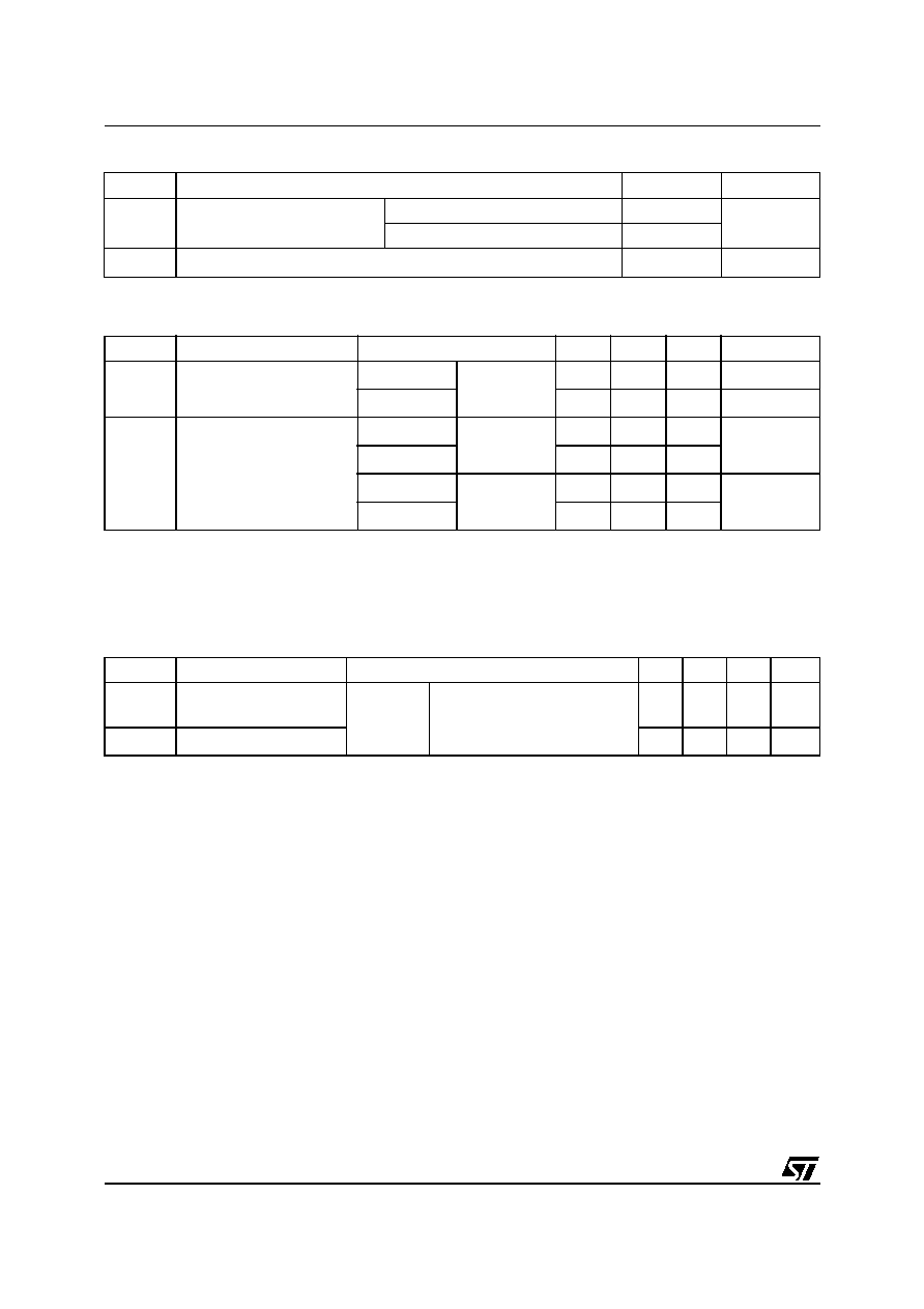
Figure 1: Application Characteristics
Figure 2: Application Waveforms
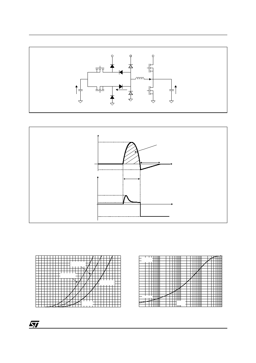
Figure 3: Forward voltage drop versus forward
current
Figure 4: Relative variation of thermal
impedance junction to case versus pulse
duration (TO-220AB / TO-247)
L
D
CL2
V
S
V
S
D
CL1
T
1
T
2
T
3
T
4
C
panel
V
Cpanel
C
S
V /2
S
GND
D
ERC2
V
DERC1
D
ERC1
i
L
I
DERC1
t
clamp
V
DERC1
t
t
i
L
I
P
I
RM
V
FP
V
F
V /2
S
t
p
0
20
40
60
80
100
120
140
160
180
200
0.0
0.2
0.4
0.6
0.8
1.0
1.2
1.4
1.6
1.8
2.0
2.2
2.4
2.6
2.8
3.0
I
(A)
FM
T =125∞C
(typical values)
j
T =25∞C
(maximum values)
j
V
(V)
FM
T =125∞C
(maximum values)
j
0.0
0.1
0.2
0.3
0.4
0.5
0.6
0.7
0.8
0.9
1.0
1.E-04
1.E-03
1.E-02
1.E-01
1.E+00
Z
/R
th(j-c)
th(j-c)
Single pulse
t (s)
p
TO-220AB
TO-247
STTH40P03S
4/8
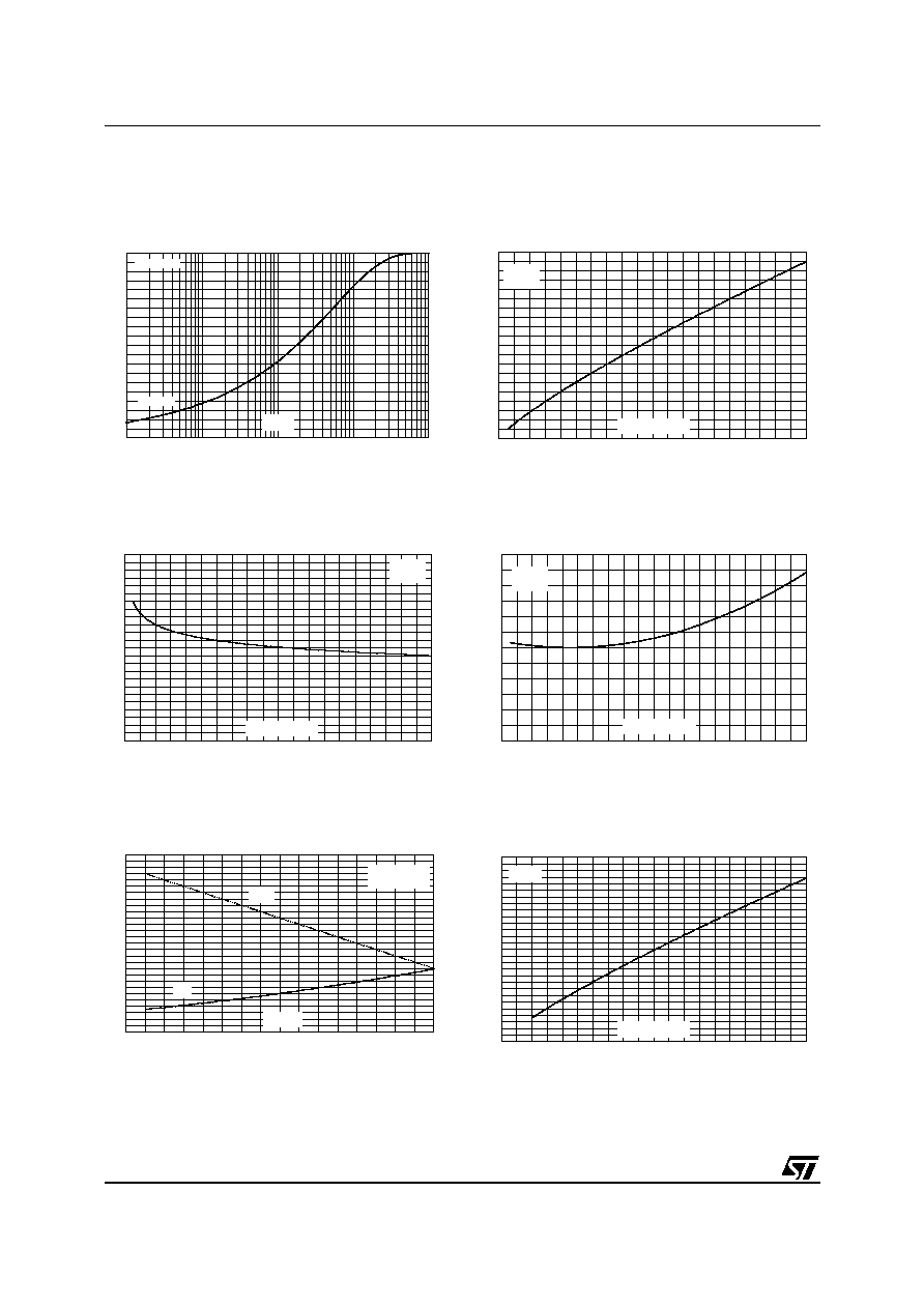
Figure 5: Relative variation of thermal
impedance junction to case versus pulse
duration (TO-220FPAB)
Figure 6: Peak reverse recovery current versus
dI
F
/dt (typical values)
Figure 7: Reverse recovery time versus dI
F
/dt
(typical values)
Figure 8: Reverse recovery softness factor
versus dI
F
/dt (typical values)
Figure 9: Relative variations of dynamic
parameters versus junction temperature
Figure 10: Transient peak forward voltage
versus dI
F
/dt (typical values)
0.0
0.1
0.2
0.3
0.4
0.5
0.6
0.7
0.8
0.9
1.0
1.E-03
1.E-02
1.E-01
1.E+00
1.E+01
Z
/R
th(j-c)
th(j-c)
Single pulse
t (s)
p
TO-220FPAB
0
2
4
6
8
10
12
14
16
18
20
0
100
200
300
400
500
600
700
800
900
1000
I
(A)
RM
dI /dt(A/µs)
F
I
I
F
F(AV)
V =100V
T =100∞C
R
j
0
5
10
15
20
25
30
35
40
45
50
55
60
0
100
200
300
400
500
600
700
800
900
1000
t (ns)
rr
dI /dt(A/µs)
F
I
I
F
F(AV)
V =100V
T =100∞C
R
j
0.2
0.3
0.4
0.5
0.6
0.7
0.8
0
100
200
300
400
500
600
700
800
900
1000
S factor
dI /dt(A/µs)
F
I
I
F
F(AV)
V =100V
T =100∞C
R
j
0.0
0.2
0.4
0.6
0.8
1.0
1.2
1.4
1.6
1.8
2.0
2.2
2.4
2.6
2.8
20
30
40
50
60
70
80
90
100
T (∞C)
j
I =I
Reference: T =100∞C
F
F(AV)
j
V =100V
R
S factor
I
RM
0.0
0.5
1.0
1.5
2.0
2.5
3.0
3.5
4.0
4.5
5.0
5.5
6.0
6.5
7.0
0
100
200
300
400
500
600
700
800
900
1000
V
(V)
FP
dI /dt(A/µs)
F
I =I
T =100∞C
F
F(AV)
j
STTH40P03S
5/8
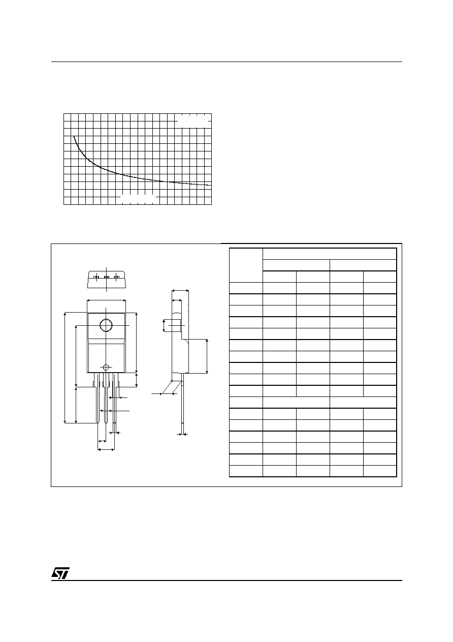
Figure 12: TO-220FPAB Package Mechanical Data
Figure 11: Forward recovery time versus dI
F
/dt
(typical values)
0
50
100
150
200
250
300
0
100
200
300
400
500
600
700
800
900
1000
t (ns)
fr
dI /dt(A/µs)
F
I =I
T =100∞C
F
F(AV)
j
V
=1.1 x V max.
FR
F
H
L3
L2
L4
L6
G
G1
F
F1
L5
D
E
L7
A
B
Dia
F2
REF.
DIMENSIONS
Millimeters
Inches
Min.
Max.
Min.
Max.
A
4.4
4.6
0.173
0.181
B
2.5
2.7
0.098
0.106
D
2.5
2.75
0.098
0.108
E
0.45
0.70
0.018
0.027
F
0.75
1
0.030
0.039
F1
1.15
1.70
0.045
0.067
F2
1.15
1.70
0.045
0.067
G
4.95
5.20
0.195
0.205
G1
2.4
2.7
0.094
0.106
H
10
10.4
0.393
0.409
L2
16 Typ.
0.63 Typ.
L3
28.6
30.6
1.126
1.205
L4
9.8
10.6
0.386
0.417
L5
2.9
3.6
0.114
0.142
L6
15.9
16.4
0.626
0.646
L7
9.00
9.30
0.354
0.366
Dia.
3.00
3.20
0.118
0.126
STTH40P03S
6/8
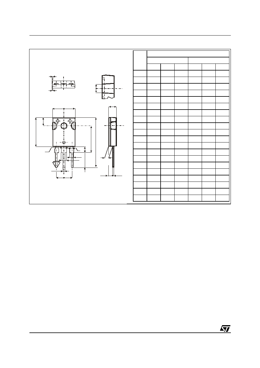
Figure 13: TO-247 Package Mechanical Data
F2
F1
V2
L4
L2
L1
L3
D
L
L5
M
E
H
V
V
A
Dia.
F3
F4
G
= =
F(x3)
REF.
DIMENSIONS
Millimeters
Inches
Min.
Typ.
Max.
Min.
Typ.
Max.
A
4.85
5.15
0.191
0.203
D
2.20
2.60
0.086
0.102
E
0.40
0.80
0.015
0.031
F
1.00
1.40
0.039
0.055
F1
3.00
0.118
F2
2.00
0.078
F3
2.00
2.40
0.078
0.094
F4
3.00
3.40
0.118
0.133
G
10.90
0.429
H
15.45
15.75 0.608
0.620
L
19.85
20.15 0.781
0.793
L1
3.70
4.30
0.145
0.169
L2
18.50
0.728
L3
14.20
14.80 0.559
0.582
L4
34.60
1.362
L5
5.50
0.216
M
2.00
3.00
0.078
0.118
V
5∞
5∞
V2
60∞
60∞
Dia.
3.55
3.65
0.139
0.143
STTH40P03S
7/8
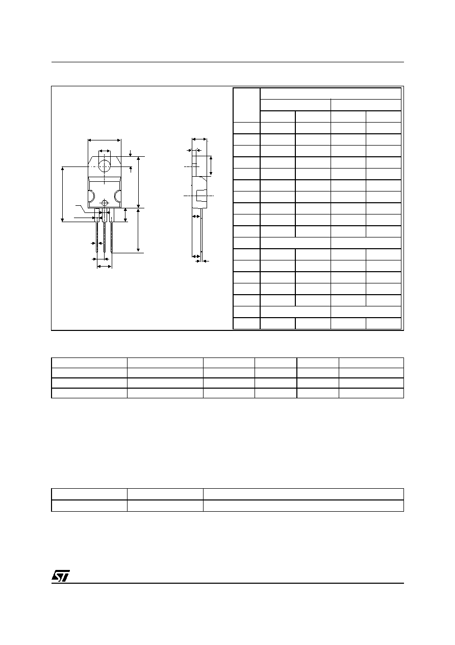
Figure 14: TO-220AB Package Mechanical Data
A
C
D
L7
Dia
L5
L6
L9
L4
F
H2
G
G1
L2
F2
F1
E
M
Table 7: Ordering Information
Epoxy meets UL94, V0
Cooling method: by conduction (C)
Recommended torque value: 0.55 m.N.
Maximum torque value: 0.70 m.N.
Ordering type
Marking
Package
Weight
Base qty
Delivery mode
STTH40P03ST
STTH40P03S
TO-220AB
2.23 g
50
Tube
STTH40P03SFP
STTH40P03S
TO-220FPAB
2.0 g
50
Tube
STTH40P03SW
STTH40P03S
TO-247
4.36 g
30
Tube
Table 8: Revision History
Date
Revision
Description of Changes
06-Jul-2005
1
First issue.
REF.
DIMENSIONS
Millimeters
Inches
Min.
Max.
Min.
Max.
A
4.40
4.60
0.173
0.181
C
1.23
1.32
0.048
0.051
D
2.40
2.72
0.094
0.107
E
0.49
0.70
0.019
0.027
F
0.61
0.88
0.024
0.034
F1
1.14
1.70
0.044
0.066
F2
1.14
1.70
0.044
0.066
G
4.95
5.15
0.194
0.202
G1
2.40
2.70
0.094
0.106
H2
10
10.40
0.393
0.409
L2
16.4 typ.
0.645 typ.
L4
13
14
0.511
0.551
L5
2.65
2.95
0.104
0.116
L6
15.25
15.75
0.600
0.620
L7
6.20
6.60
0.244
0.259
L9
3.50
3.93
0.137
0.154
M
2.6 typ.
0.102 typ.
Diam.
3.75
3.85
0.147
0.151

STTH40P03S
8/8
Information furnished is believed to be accurate and reliable. However, STMicroelectronics assumes no responsibility for the consequences
of use of such information nor for any infringement of patents or other rights of third parties which may result from its use. No license is granted
by implication or otherwise under any patent or patent rights of STMicroelectronics. Specifications mentioned in this publication are subject
to change without notice. This publication supersedes and replaces all information previously supplied. STMicroelectronics products are not
authorized for use as critical components in life support devices or systems without express written approval of STMicroelectronics.
The ST logo is a registered trademark of STMicroelectronics.
All other names are the property of their respective owners
© 2005 STMicroelectronics - All rights reserved
STMicroelectronics group of companies
Australia - Belgium - Brazil - Canada - China - Czech Republic - Finland - France - Germany - Hong Kong - India - Israel - Italy - Japan -
Malaysia - Malta - Morocco - Singapore - Spain - Sweden - Switzerland - United Kingdom - United States of America
www.st.com