STV2112B
BUS-CONTROLLED PAL/SECAM TV PROCESSOR
August 1998
1
2
3
4
5
6
7
8
9
10
11
12
13
14
15
16
17
18
19
20
21
22
23
24
25
26
27
28
29
30
31
32
33
34
35
36
37
38
39
40
41
42
GND1
Y/CVBS
BEXT
FBOSD
ROS D
GOSD
BOS D
S WI
VOL
FTUN2
FTUN1
S CL
SDA
ACC
CLPF
CXTL1
S ELECT
GND2
V
C C2
BYO
RYO
LFB/S C
HOUT
VOUT
VAMP
S LPF
S XTL
BCL
ICAT
RO
GO
BO
CR
CB
CG
CHR/SVHS
V
C C1
CHROMA/SCANNING/BUS S UP P LY
BYI
RYI
B-Y OUTPUT
R-Y OUTP UT
R-Y INPUT
B-Y INPUT
LINE FLYBACK INPUT/SANDCASTLE OUTP UT
HORIZONTAL OUTP UT
VERTICAL OUTP UT
AMPLITUDE CONTROL VOLTAGE
S CANNING LOOP FILTER
503kHz CERAMIC
BEAM CURRENT LIMITER
CATHODE CURRENT MEASUREMENT
RED OUTP UT
GREEN OUTP UT
BLUE OUTP UT
RED CUT-OFF CAPACITOR
BLUE CUT-OFF CAPACITOR
GREEN CUT-OFF CAPACITOR
CHROMINANCE INPUT/SVHS S ELECTION
VIDEO S UPP LY
BUS/VIDEO GROUND
CVBS OR LUMINANCE INPUT
EXTERNAL BLUE INPUT
OS D RGB INSERTION
OS D BLUE INPUT
IF STANDARD AND S WITCH S ELECTION
VOLUME AND MUTE CONTROL VOLTAGE
FILTER TUNING
DATA WIRE I
2
C BUS
ACC CONTROL CAPACITOR
CHROMA LOOP FILTER
XTAL2 S ELECTION
CHROMA/SCANNING GROUND
4.43 MHz XTAL
CLOCK WIRE I
2
C BUS
CLOCHE FILTER TUNING
OS D GREEN INPUT
OS D RED INPUT
GEXT
REXT
FBEXT
EXTERNAL GREEN INPUT
EXTERNAL RED INPUT
EXTERNAL RGB INSERTION
21
12
B
-
01.
E
P
S
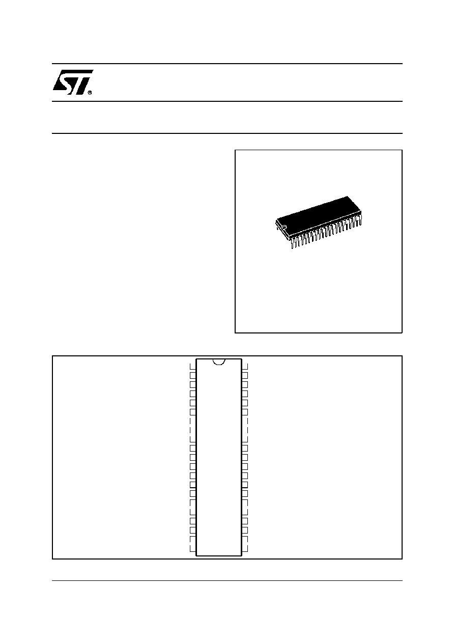
PIN CONNECTIONS
SHRINK42
(Plastic Package)
ORDER CODE : STV2112B
.
I
2
C BUS CONTROL OF ALL FUNCTIONS
.
INTEGRATED FILTERS
(TRAP, BANDPASS, CLOCHE)
.
INTEGRATED LUMINANCE DELAY LINE
.
PAL/SECAM CHROMA DEMODULATORS
.
AUTOMATIC CUT-OFF CURRENT LOOP
.
TWO RGB INPUTS
.
SVHS SWITCH
.
TWO PLLs HORIZONTAL DEFLECTION
.
VERTICAL COUNT DOWN
.
VERY FEW EXTERNAL COMPONENTS
DESCRIPTION
The STV2112B is a fully bus controlled IC for TV
luma, chroma and deflection processing.
Used with STV8224 (PIF/SIF/switches), TDA1771
or TDA8174 (frame booster),STV2180 (delay line),
it allows to design a PAL/SECAM(BGDKIL) set with
very few external components and no adjustment.
1/24
Y
CHR
FB
RG
BF
B
RG
B
Y/CVBS
CHR
ACC
SELECT
CXTAL1
R
G
B
ICAT
CR
CG
CB
BCL
VOUT
HOUT
SXTAL
SLPF
LFB/SC
GND2
SWI
VOL
CLPF
R-Y
B-Y
FILTER
TUNING
V
CC1
SDA
SCL
CLOCHE
TUNING
SHARP
V
CC2
GND1
FILTER
TUNING
TRAP
BANDPASS
CLOCHE
SVHS
SWITCH
20
23
89
DELAY
LINE
SHARPNESS
MATRIX
SATURATION
BRIGHTNESS
CONTRAST
RGB
SWITCHES
Contrast
BLANKING
AUTO
CUT-OFF
BLACK
&
WHITE
CONTROL
22
42
19
18
17
16
39
38
R-Y
B-Y
EXTERNAL
OSD
15
14
13
12
29
28
27
30
26
24
25
31
35
VAMP
34
FRAME
SCANNING
LINE
SCANNING
36
21
1
37
33
32
SYNC
SEPARATOR
STANDARD
IDENTIFICATION
ACC
5
PAL
KILLER
SECAM
KILLER
SECAM
DEMODULATORS
PAL
DEMODULATORS
DELAY
LINE
INTERFACE
2
3
44
0
4
1
BUS
DECODER
6
7
11
10
BRIG
SAT
CONT
STD
DRIVE
VIDEO
IDENTIFICATION
CUT-OF
F
STV2112B
PLL
211
2B
-
02.
E
P
S
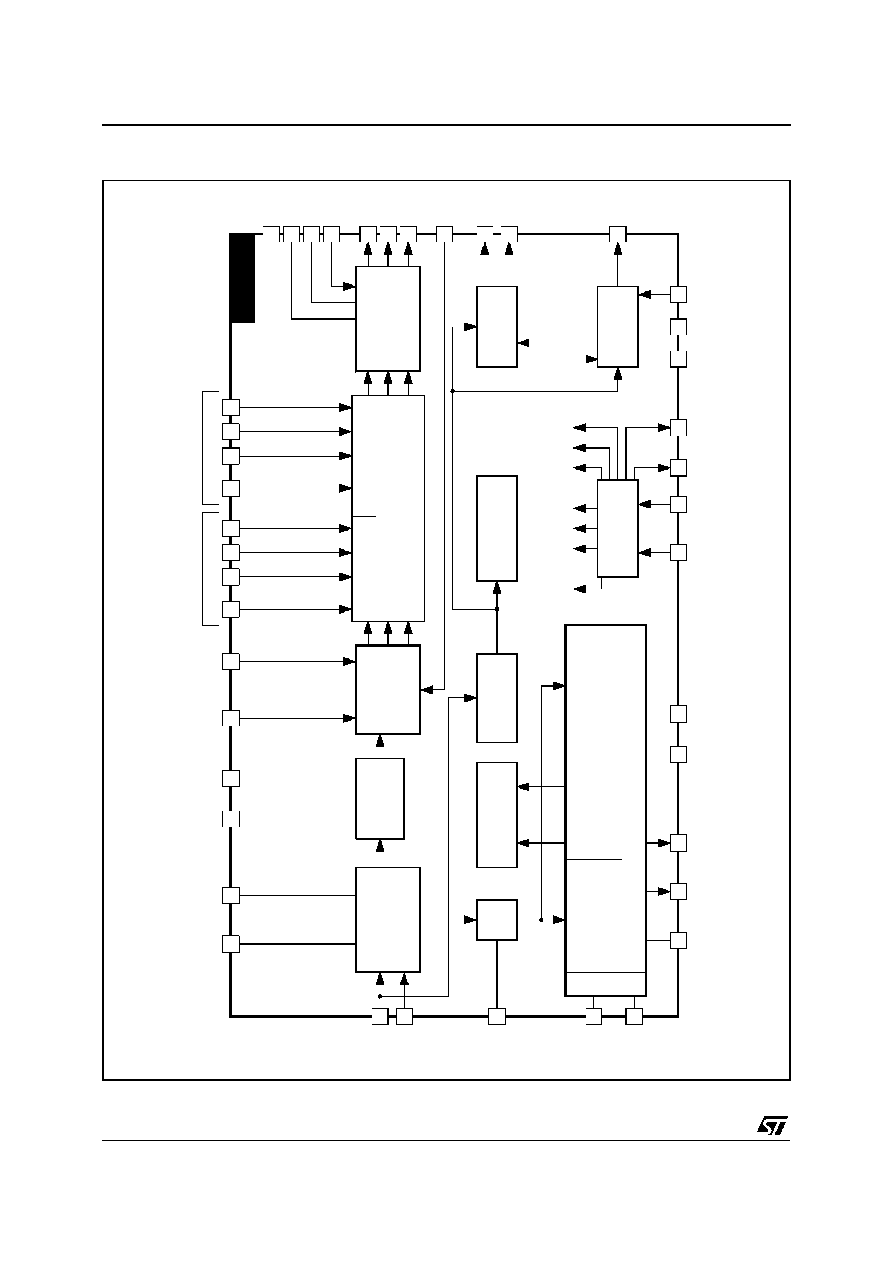
BLOCK DIAGRAM
STV2112B
2/24

FUNCTIONAL DESCRIPTION
1 - DEFLECTION CIRCUIT
Note : [X,Y] : line number referred to the internal
line counter numbering
- Fully integrated synch. separator, with a low pass
filter, a black level alignment of the Y/CVBS input, a
slicing level at 2/3,1/3of the sync. pulse amplitude.
- Frame sync. pulse locked on 2 f
H
frequency to
perfect interlace.
- 500kHz VCO with an external ceramic resonator.
- Two phase locked loops
�
the first PLL locks the VCO on the video signal
frequency,
�
the second PLL compensates the line transistor
storage time.
- Three time constants for the first PLL.
�
thelong timeconstantis usedfor normal operation
�
the short time constant is automatically used
during the frame retrace and in search mode of
VCR when the frame pulse is outside [258,264]
and [309,314].
�
very long time constant when no video recognition
Time constants in normal operation
(automatic selection of time constants) :
50Hz input signal :
- short time constant : [306, 21]
- long time constant : the rest of the field
�
inhibition of the first PLL :
the first locked loop is opened from line 309 to
line 4.5 (or 314) in 50Hz mode.
�
the time constantsvalues are chosenby means
of external components.
�
possibility to force the short time constant
through the bus.
�
possibility to force the very long time constant
through the bus.
- Video identification : coincidence detector be-
tween the line synchro top and a line frequency
window from the first PLL. The video identification
status is available in the output register of the I
2
C
bus decoder.
- Generation of burst gate pulses and line fre-
quency signals from the first PLL to drive the
chroma and video circuits. The burst gate pulse
is also sent to the sandcastle generator.
- Frame synchro window :
[248, 352]
catching
- Field frequency selection windows :
[288, 352]
50Hz mode selection window
- frame blanking pulse :
from line 0 to 21 in 50Hz mode
- Vertical output pulse is 10.5 lines long.
- Horizontal output pulse : 28
�
s line pulse on an
open collector output;
- Start up circuit : the horizontal output is at a high
level when V
CC
increases from 0 to 6.8V. On
shutting down, horizontal pulses are disabled
when V
CC
is below 6.2V.
- Soft-start circuit : the duty cycle of the horizontal
output is 78 % (Thigh/(Thigh + TLow)) when V
CC1
is lower than (0.75 x V
CC2
), during the rising time.
During the falling time, a 78% duty cycle HOUT
pulse is provided when V
CC1
is lower than
(0.60 x V
CC2
).
- Possibility to disable the horizontal output pulse
through the bus (force a high level on HOUT).
- Horizontal position adjustment controlled by bus.
- Bus controlledoutput voltage to adjustthe vertical
amplitude ; this voltagepermitsto adjustthe slope
of the vertical sawtooth generated by the external
frame booster.
- Bus controlled vertical position ; the high level of
the vertical pulse permits to adjust the vertical
position.
- Bus controlled 4/3-16/9 selection : the low level
of the vertical pulse is 0.1V when 16/9 is selected,
2V when 4/3 is selected.
- Combined flyback input and sandcastle output
(Pin 37). Two thresholds on LFB/SCO Pin : The
lowest threshold (0.7V) permits to extract the line
blanking pulse ; the highest threshold (2V) per-
mits to extract the line pulse for PLL2. The sand-
castle signal at Pin 37 is used to control the
external baseband chroma delay line.
2 - FILTERS
- Integrated trap filter :
Q
=
1
f
o
f
-
3dB
-
f
-
3dB
f
o
Q = 1.7 at sharp. min
Q = 3.0 at sharp. max
Center frequency :
- 4.43MHz for PAL
- 4.25MHz, for SECAM (f
-3dB
= 3MHz; -20dB
rejection between 4.1MHz and 4.4MHz)
- Integrated chroma bandpass :
Q = 3.5, Center frequency= 4.43MHz
- Integrated cloche filter for SECAM :
Q = 16, Center frequency = 4.286MHz
- Integrated delay line : Bandwidth = 8MHz
- Integrated low pass filter for deflection part.
- Allfilters aretunedwitha referencephaselockedloop.
The PLL consists of a lowpass filter, a phasecompa-
rator,a loopfilter (with an externalcapacitor).The ref-
erence signal is the continuouscarrier wave from the
VCO (4.43MHz). The PLL adjusts the center fre-
quency of the lowpass so that it is equal to the
referencesignal.ThetuningvoltageofthePLLisused
to adjust all other filters. The cloche filter is fine tuned
with a secondPLLoperatingduring frame retrace.
STV2112B
3/24

3 - VIDEO CIRCUIT
- 2 RGB inputs : RGB (OSD) input has priority
against the RGBext. Maximum contrast on RGB
(OSD). -12dB range contrast control on RGBext.
Possibility to disable the RGBext insertion
through the bus.
- Oversize blanking capability on FB(OSD)(Pin15)
input. The RGB ouputs will be blanked when the
voltage on Pin 15 will exceed the second thresh-
old at 1.9V (blanking threshold) : the whole field
is blanked but not the inserted cut-off pulses. The
OSD insertion threshold is 0.7V.
- Automatic cut-off current loop : 2V cut-off range.
Sequential cut-off current measurement during
the three lines after the frame blanking signal.
Leakage current measurement during the frame
blanking, memorization on an internal capacitor.
- Warm up detector.
- Beam current limiter DC voltage input.
The beam current limiter control voltage will act
on contrast first, then the brightness will be de-
creased when contrast attenuationreaches -5dB.
- Bus control of the red, green and blue channel
gain (White point adjustment)
- Bus control of the red and green DC levels (black
point adjustment)
- PAL and SECAM matrix).
- Switch-off of the trap filter in SVHS mode.
- Bus controlled contrast on luminance (20dB range)
- Bus controlled saturation (50dB range)
- Bus controlled brightness : 40% range at maxi-
mum contrast.
- Bus controlled sharpness (peaking) ; sharpness
active in PAL standard only.
- Noise coring function on sharpness.
4 - CHROMA CIRCUIT
4.1 - PAL/SECAM Decoders
- SVHS inputs ; bus controlled SVHS mode.
- 30dB range ACC
- Use of an external base band delay line
(STV2180 recommended)
- Automatic standard identification, with possibility
to force the standard through the bus.
4.2 - PAL Decoder
- ACC done by peak detector on synchronous de-
modulation of the burst
- Fully integrated killer functions.
- VCO using crystal 4.43MHz
XTAL SPECIFICATION :
Frequency :
4.433619MHz (PAL/SECAM)
Vibration mode : Fondamental,series resonance
(no serial capacitor)
Motional capacity : 13fF
�
3fF
Resonance resistance : < 70
Shunt capacitance : < 7pF
Spurious response : No resonance at 3*f
o
�
3kHz
- 0
o
and
�
90
o
demodulation angles for PAL
4.3 - SECAM Decoder
- ACC
- Fully integrated killer
- Two integrated discriminators with two PLL
- Integrated deemphasis
4.4 - Standard Identification
- Sequential identification.
- 2 identification sequences :
PAL mode, SECAM mode
- PAL priority
- the SECAM mode is locked after two identified
SECAM sequences
- the SECAM mode can be selected in 50Hz only
- Blanking of the (R-Y) and B-Y) outputs during
color search mode.
5 - OTHER FUNCTIONS : IF CONTROLS
5.1 - Volume Control and Mute
The volume control voltage range on Pin 10 is from
0.5V to 5V.
A low voltage on Pin 10 (below 0.2V) will mute the
FM demodulator of the IF circuit STV8224.
It will put the volume at the minimum level and thus
there will be no soundeither in TV mode or SCART
mode.
The volume control voltage and the mute level are
controlled by the bus.
5.2 - IF Standard and TV/SCART Mode Selection
The selection of IF standard (positive or negative
vision modulation)and theTV/SCARTmode is con-
trolled by the bus. The selection is convertedin four
voltages on Pin 21.
The lowest voltage selects the TV mode and the
NEGATIVE vision modulation.
The highest voltage (open collector output with
internal pull-up resistor to V
CC
) selects the SCART
mode and the NEGATIVE vision modulation.
The two other intermediate voltages select either
TV mode and POSITIVE vision modulation or
SCART mode and POSITIVE vision modulation.
FUNCTIONAL DESCRIPTION (continued)
STV2112B
4/24
I
2
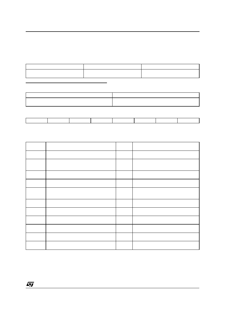
C BUS SPECIFICATION
General Comments
Slave Address : 8A (HEX) (1000101X)
WRITE MODE DATA FORMAT
Slave Address
Register Address
Data
1000 1010
(8A)
XXXS SSSS
(from 00 to 11HEX)
XXSS SSSS
(6 significant bits Max.)
The not used bits in data byte must be put to "0".
READ MODE DATA FORMAT
Slave Address
Data
1000 1011
(8B)
SSSS SSSS
(8 significant bits)
MSB on the left, LSB on the Right.
MSB
LSB
X
X
X
X
X
X
X
X
X : not significant bit - S : significant bit
Input Signals (Write Mode)
VIDEO
Address
Dec (HEX)
Description
Data
(Bits)
Comments
0 (00)
Contrast
5
XXX0 0000 = -20dB
XXX1 1111 = 0dB
0 (00)
External Fast Blanking Enable
1
XXSX XXXX
0 = RGBext insertion enable
1 = RGBext insertion disable
1 (01)
Saturation
6
XX00 0000 = -44dB
XX11 1111 = +6dB
2 (02)
Brightness
5
XXX0 0000 = -20%
XXX1 1111 = +20%
2 (02)
RGB Outputs Blanking
1
XXSX XXXX
0 = Normal mode
1 = Blanking active
3 (03)
Red Drive Adjust (white point red adjust)
6
XX00 0000 = -6dB
XX11 1111 = 0dB
4 (04)
Red Cut-off Adjust
6
XX00 0000 = +150mV
XX11 1111 = -150mV
5 (05)
Green Drive Adjust (white point green adjust)
6
XX00 0000 = -6dB
XX11 1111 = 0dB
6 (06)
Green Cut-off Adjust
6
XX00 0000 = +150mV
XX11 1111 = -150mV
7 (07)
Blue Drive Adjust (white point blue adjust)
6
XX00 0000 = -6dB
XX11 1111 = 0dB
8 (08)
Sharpness
3
XXXX X000 = Peaking Min.
XXXX X111 = Peaking Max.
STV2112B
5/24