Version 4.2
April 2000
1/43
STV6886
LOW-COST I
2
C CONTROLLED DEFLECTION PROCESSOR
FOR MULTISYNC MONITOR
FEATURES
General
s
SYNC PROCESSOR (separate or composite)
s
12V SUPPLY VOLTAGE
s
8V REFERENCE VOLTAGE
s
HOR. LOCK/UNLOCK OUTPUT
s
HOR. & VERT. LOCK/UNLOCK INDICATION
s
READ/WRITE I
2
C INTERFACE
s
HORIZONTAL AND VERTICAL MOIRE
s
B+ REGULATOR
- Internal PWM generator for B+ current mode
step-up converter
- Switchable to step-down converter
- I
2
C-adjustable B+ reference voltage
- Output pulses synchronized on horizontal
frequency
- Internal maximum current limitation.
Horizontal
s
Self-adaptative
s
Dual PLL concept
s
80kHz maximum frequency
s
X-ray protection input
s
I
2
C controls: Horizontal duty-cycle, H-position,
horizontal size amplitude
Vertical
s
Vertical ramp generator
s
50 to 120 Hz agc loop
s
Geometry tracking with VPOS & VAMP
s
I
2
C controls:VAMP, VPOS, S-CORR, C-CORR
s
Vertical breathing compensation
I
2
C Geometry Corrections
s
Vertical parabola generator (Pin Cushion - E/W,
Keystone, Corner Correction)
s
Horizontal dynamic phase
(Side Pin Balance & Parallelogram)
s
Horizontal
and
vertical
dynamic
focus
(Horizontal Focus Amplitude, Horizontal Focus
Symmetry, Vertical Focus Amplitude)
DESCRIPTION
The STV6886 is a monolithic integrated circuit as-
sembled in a 32-pin shrink dual-in-line plastic
package. This IC controls all the functions related
to horizontal and vertical deflection in multimode
or multi-frequency computer display monitors.
The internal sync processor, combined with the
powerful geometry correction block, makes the
STV6886 suitable for very high performance mon-
itors, using few external components.
Combined with other ST components dedicated
for CRT monitors (microcontroller, video preampli-
fier, video amplifier, OSD controller) the STV6886
allows fully I
2
C bus-controlled computer display
monitors to be built with a reduced number of ex-
ternal components.
PIN CONNECTIONS
SHRINK32 (Plastic Package)
ORDER CODE: STV6886
H/HVIN
VSYNCIN
HMOIRE/HLOCK
PLL2C
C0
R0
PLL1F
HPOSITION
HFOCUSCAP
FOCUS-OUT
HGND
HFLY
HREF
COMP
REGIN
I
SENSE
5V
SDA
SCL
V
CC
BOUT
GND
HOUT
XRAY
EWOUT
VOUT
VCAP
V
REF
VAGCCAP
VGND
VBREATH
B + GND
1
2
3
4
5
6
7
8
9
10
11
12
13
14
15
16
17
18
19
20
21
22
23
24
25
26
27
28
29
30
31
32
1

TABLE OF CONTENTS
2
2/43
PIN CONNECTIONS . . . . . . . . . . . . . . . . . . . . . . . . . . . . . . . . . . . . . . . . . . . . . . . . . . . . . . . . . . . . 3
QUICK REFERENCE DATA . . . . . . . . . . . . . . . . . . . . . . . . . . . . . . . . . . . . . . . . . . . . . . . . . . . . . . . 4
BLOCK DIAGRAM . . . . . . . . . . . . . . . . . . . . . . . . . . . . . . . . . . . . . . . . . . . . . . . . . . . . . . . . . . . . . . 5
ABSOLUTE MAXIMUM RATINGS . . . . . . . . . . . . . . . . . . . . . . . . . . . . . . . . . . . . . . . . . . . . . . . . . . 6
THERMAL DATA . . . . . . . . . . . . . . . . . . . . . . . . . . . . . . . . . . . . . . . . . . . . . . . . . . . . . . . . . . . . . . . 6
Supply and reference voltages . . . . . . . . . . . . . . . . . . . . . . . . . . . . . . . . . . . . . . . . . . . . . . . . . . . . . 6
I2C READ/WRITE . . . . . . . . . . . . . . . . . . . . . . . . . . . . . . . . . . . . . . . . . . . . . . . . . . . . . . . . . . . . . . . 7
SYNC PROCESSOR . . . . . . . . . . . . . . . . . . . . . . . . . . . . . . . . . . . . . . . . . . . . . . . . . . . . . . . . . . . . 7
HORIZONTAL SECTION . . . . . . . . . . . . . . . . . . . . . . . . . . . . . . . . . . . . . . . . . . . . . . . . . . . . . . . . . 8
VERTICAL SECTION . . . . . . . . . . . . . . . . . . . . . . . . . . . . . . . . . . . . . . . . . . . . . . . . . . . . . . . . . . . 10
DYNAMIC FOCUS SECTION . . . . . . . . . . . . . . . . . . . . . . . . . . . . . . . . . . . . . . . . . . . . . . . . . . . . . 11
GEOMETRY CONTROL SECTION . . . . . . . . . . . . . . . . . . . . . . . . . . . . . . . . . . . . . . . . . . . . . . . . 12
MOIRE CANCELLATION SECTION . . . . . . . . . . . . . . . . . . . . . . . . . . . . . . . . . . . . . . . . . . . . . . . . 13
B+ SECTION . . . . . . . . . . . . . . . . . . . . . . . . . . . . . . . . . . . . . . . . . . . . . . . . . . . . . . . . . . . . . . . . . . 14
TYPICAL OUTPUT WAVEFORMS . . . . . . . . . . . . . . . . . . . . . . . . . . . . . . . . . . . . . . . . . . . . . . . . . 16
I2C BUS ADDRESS TABLE . . . . . . . . . . . . . . . . . . . . . . . . . . . . . . . . . . . . . . . . . . . . . . . . . . . . . . 20
OPERATING DESCRIPTION . . . . . . . . . . . . . . . . . . . . . . . . . . . . . . . . . . . . . . . . . . . . . . . . . . . . . 23
1 GENERAL CONSIDERATIONS . . . . . . . . . . . . . . . . . . . . . . . . . . . . . . . . . . . . . . . . . . . . . . 23
1.1
Power Supply . . . . . . . . . . . . . . . . . . . . . . . . . . . . . . . . . . . . . . . . . . . . . . . . . . . . . . 23
1.2
I
2
C Control . . . . . . . . . . . . . . . . . . . . . . . . . . . . . . . . . . . . . . . . . . . . . . . . . . . . . . . . 23
1.3
Write Mode . . . . . . . . . . . . . . . . . . . . . . . . . . . . . . . . . . . . . . . . . . . . . . . . . . . . . . . . 23
1.4
Read Mode . . . . . . . . . . . . . . . . . . . . . . . . . . . . . . . . . . . . . . . . . . . . . . . . . . . . . . . 23
1.5
Sync Processor . . . . . . . . . . . . . . . . . . . . . . . . . . . . . . . . . . . . . . . . . . . . . . . . . . . . 23
1.6
Sync Identification Status . . . . . . . . . . . . . . . . . . . . . . . . . . . . . . . . . . . . . . . . . . . . . 23
1.7
IC status . . . . . . . . . . . . . . . . . . . . . . . . . . . . . . . . . . . . . . . . . . . . . . . . . . . . . . . . . . 24
1.8
Sync Inputs . . . . . . . . . . . . . . . . . . . . . . . . . . . . . . . . . . . . . . . . . . . . . . . . . . . . . . . 24
1.9
Sync Processor Output . . . . . . . . . . . . . . . . . . . . . . . . . . . . . . . . . . . . . . . . . . . . . . 24
2 HORIZONTAL PART . . . . . . . . . . . . . . . . . . . . . . . . . . . . . . . . . . . . . . . . . . . . . . . . . . . . . . 24
2.1
Internal Input Conditions . . . . . . . . . . . . . . . . . . . . . . . . . . . . . . . . . . . . . . . . . . . . . 24
2.2
PLL1 . . . . . . . . . . . . . . . . . . . . . . . . . . . . . . . . . . . . . . . . . . . . . . . . . . . . . . . . . . . . . 25
2.3
PLL2 . . . . . . . . . . . . . . . . . . . . . . . . . . . . . . . . . . . . . . . . . . . . . . . . . . . . . . . . . . . . . 26
2.4
Output Section . . . . . . . . . . . . . . . . . . . . . . . . . . . . . . . . . . . . . . . . . . . . . . . . . . . . . 27
2.5
X-RAY Protection . . . . . . . . . . . . . . . . . . . . . . . . . . . . . . . . . . . . . . . . . . . . . . . . . . . 27
2.6
Horizontal and Vertical Dynamic Focus . . . . . . . . . . . . . . . . . . . . . . . . . . . . . . . . . . 27
2.7
Horizontal Moir� Output . . . . . . . . . . . . . . . . . . . . . . . . . . . . . . . . . . . . . . . . . . . . . . 29
3 VERTICAL PART . . . . . . . . . . . . . . . . . . . . . . . . . . . . . . . . . . . . . . . . . . . . . . . . . . . . . . . . . 29
3.1
Function . . . . . . . . . . . . . . . . . . . . . . . . . . . . . . . . . . . . . . . . . . . . . . . . . . . . . . . . . . 29
3.2
I2C Control Adjustments . . . . . . . . . . . . . . . . . . . . . . . . . . . . . . . . . . . . . . . . . . . . . 29
3.3
Vertical Moir� . . . . . . . . . . . . . . . . . . . . . . . . . . . . . . . . . . . . . . . . . . . . . . . . . . . . . . 29
3.4
Basic Equations . . . . . . . . . . . . . . . . . . . . . . . . . . . . . . . . . . . . . . . . . . . . . . . . . . . . 30
3.5
Geometric Corrections . . . . . . . . . . . . . . . . . . . . . . . . . . . . . . . . . . . . . . . . . . . . . . . 30
3.6
E/W . . . . . . . . . . . . . . . . . . . . . . . . . . . . . . . . . . . . . . . . . . . . . . . . . . . . . . . . . . . . . 31
3.7
Dynamic Horizontal Phase Control . . . . . . . . . . . . . . . . . . . . . . . . . . . . . . . . . . . . . 32
4 DC/DC CONVERTER PART . . . . . . . . . . . . . . . . . . . . . . . . . . . . . . . . . . . . . . . . . . . . . . . . 32
4.1
Step-up Configuration . . . . . . . . . . . . . . . . . . . . . . . . . . . . . . . . . . . . . . . . . . . . . . . 32
4.2
Step-down Configuration . . . . . . . . . . . . . . . . . . . . . . . . . . . . . . . . . . . . . . . . . . . . . 32
4.3
Step-up and Step-down Configuration Comparison . . . . . . . . . . . . . . . . . . . . . . . . 32
INTERNAL SCHEMATICS . . . . . . . . . . . . . . . . . . . . . . . . . . . . . . . . . . . . . . . . . . . . . . . . . . . . . . . 34
PACKAGE MECHANICAL DATA . . . . . . . . . . . . . . . . . . . . . . . . . . . . . . . . . . . . . . . . . . . . . . . . . . 41
STV6886
3/43
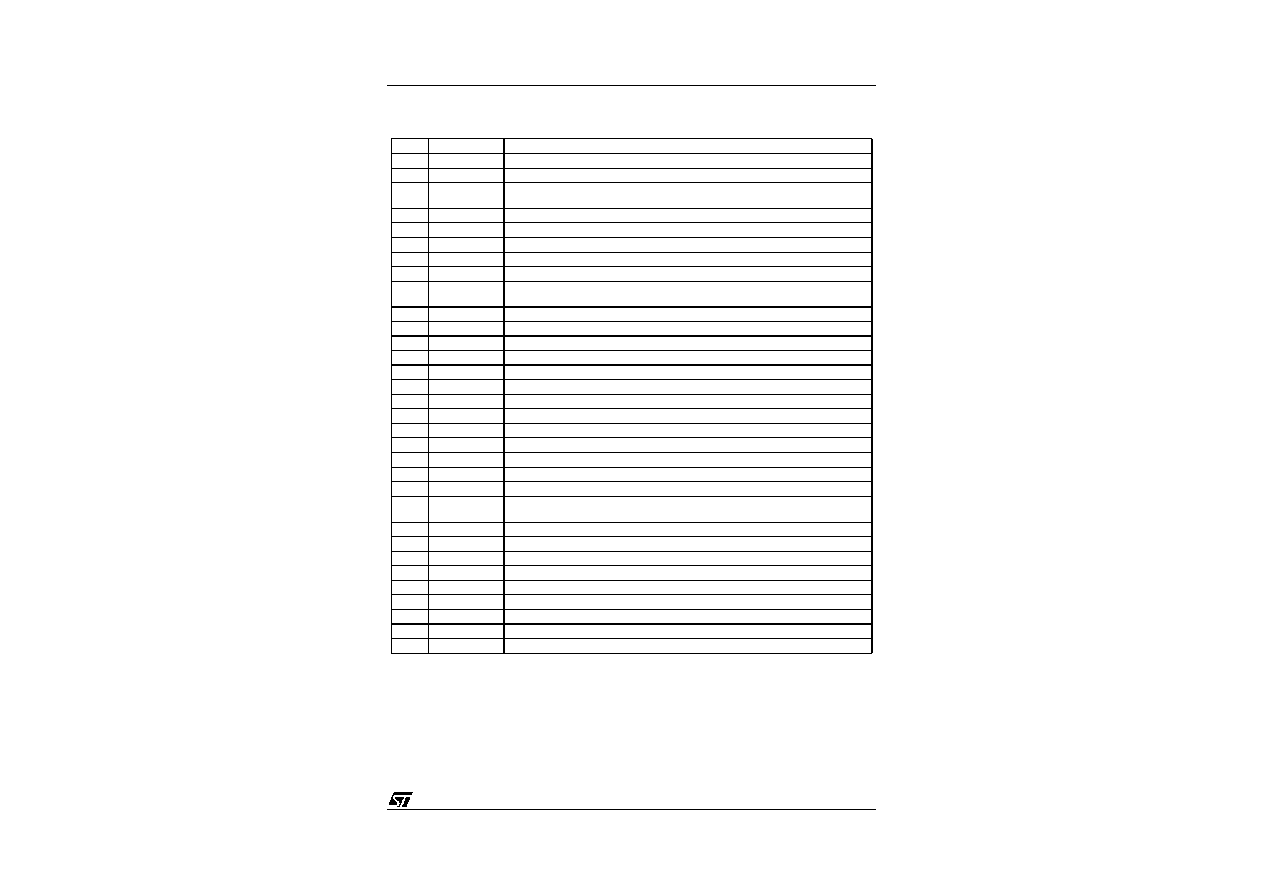
PIN CONNECTIONS
Pin
Name
Fun ction
1
H/HVIN
TTL-compatible Horizontal sync Input (separate or composite)
2
VSYNCIN
TTL-compatible Vertical sync Input (for separated H&V)
3
HMOIRE/
HLOCK
Horizontal Moir� Output (to be connected to PLL2C through a resistor divider), HLock
Output
4
PLL2C
Second PLL Loop Filter
5
C0
Horizontal Oscillator Capacitor
6
R0
Horizontal Oscillator Resistor
7
PLL1F
First PLL Loop Filter
8
HPOSITIO N
Horizontal Position Filter (capacitor to be connected to HGND)
9
HFOCUS-
CAP
Horizontal Dynamic Focus Oscillator Capacitor
10
FOCUS OUT
Mixed Horizontal and Vertical Dynamic Focus Output
11
HGND
Horizontal Section Ground
12
HFLY
Horizontal Flyback Input (positive polarity)
13
HREF
Horizontal Section Reference Voltage (to be filtered)
14
COMP
B+ Error Amplifier Output for frequency compensation and gain setting
15
REGIN
Feedback Input of B+ control loop
16
I
SENSE
Sensing of external B+ switching transistor current, or switch for step-down converter
17
B+GND
Ground (related to B+ reference)
18
VBREATH
V Breathing Input Control (compensation of vertical amplitude against EHV variation)
19
VGND
Vertical Section Ground
20
VAGCCAP
Memory Capacitor for Automatic Gain Control in Vertical Ramp Generator
21
V
REF
Vertical Section Reference Voltage (to be filtered to pin 19)
22
VCAP
Vertical Sawtooth Generator Capacitor
23
VOUT
Vertical Ramp Output (with frequency-independent amplitude and S or C Corrections
if any). It includes vertical position and vertical moir� voltages.
24
EWOUT
Pin Cushion (E/W) Correction Parabola Output
25
XRAY
X-RAY protection input (with internal latch)
26
HOUT
Horizontal Drive Output (NPN open collector)
27
GND
General Ground
28
BOUT
B+ PWM Regulator Output (NPN open collector)
29
V
CC
Supply Voltage(12V typ) (referenced to Pin 27)
30
SCL
I
2
C Clock Input
31
SDA
I
2
C Data Input
32
5V
5V Supply Voltage
STV6886
4/43
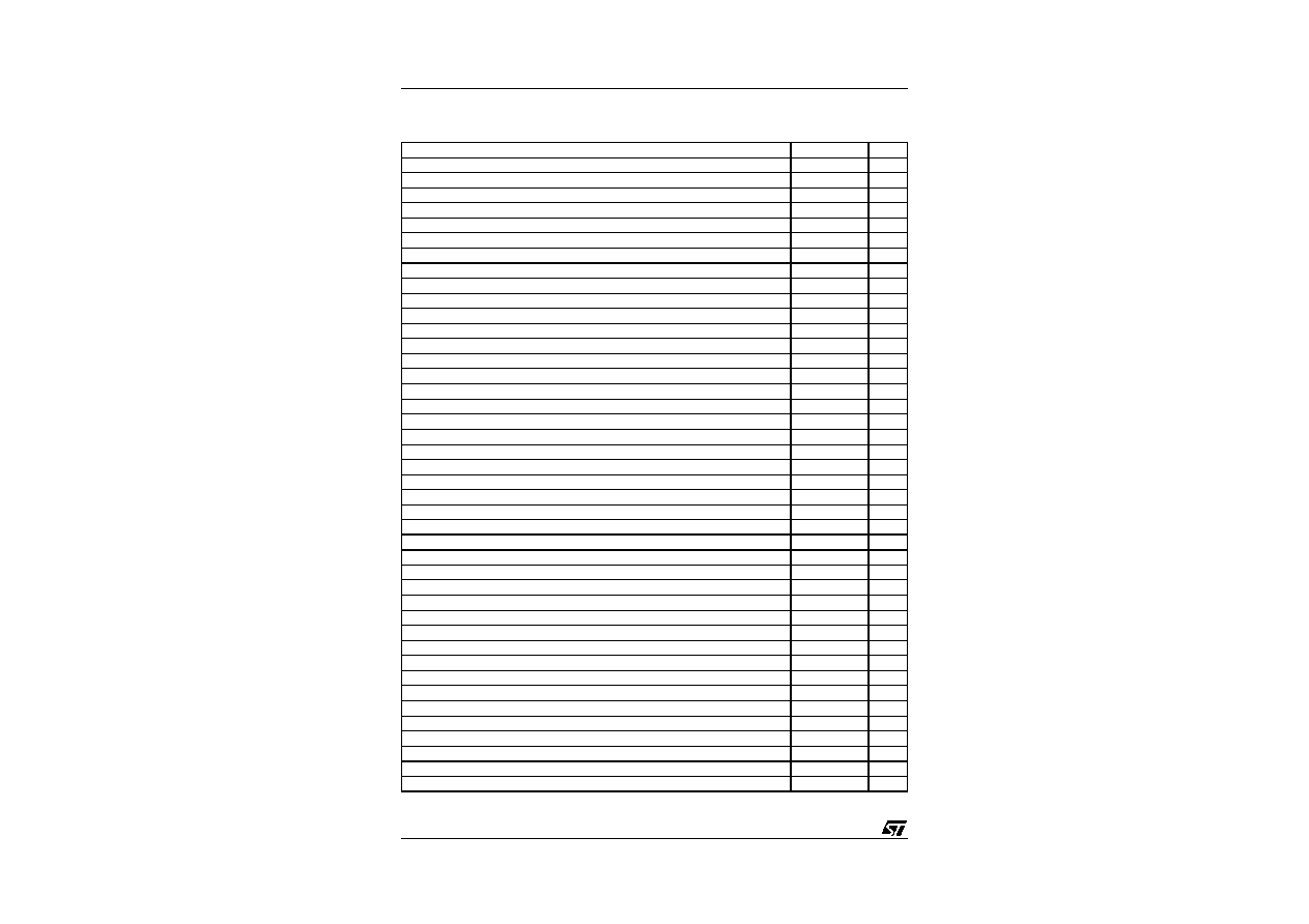
QUICK REFERENCE DATA
Parameter
Value
Unit
Any polarity on H Sync & V Sync inputs
YES
TTL or composite Syncs
YES
Sync on Green
NO
Horizontal Frequency
15 to 80
kHz
Horizontal Autosync Range (for given R0 and C0. Can be easily increased by application)
1 to 3.5 f0
Control of free-running frequency
NO
Frequency Generator for Burn-in
NO
Control of H-Position through I
2
C
YES
Control for H-Duty Cycle through I
2
C
30 to 65
%
PLL1 Inhibition Possibility
NO
Output for Horizontal Lock/Unlock
YES
Dual Polarity H-Drive Outputs
NO
Vertical Frequency
35 to 150
Hz
Vertical Autosync Range (for 150nF on Pin 22 and 470nF on Pin 20)
50 to 120
Hz
Vertical S-Correction (adapted to normal or super flat tube), controlled through I
2
C
YES
Vertical C-Correction, controlled through I
2
C
YES
Control of Vertical Amplitude through I
2
C
YES
Control of Vertical Position through I
2
C
YES
Input for Vertical Amplitude compensation versus EHV
YES
E/W Correction Output (also known as Pin Cushion Output)
YES
Horizontal Size Adjustment through I
2
C control of E/W Output DC level
YES
Control of E/W (Pincushion) Adjustment through I
2
C
YES
Control of Keystone (Trapezo�d) Adjustment through I
2
C
YES
Control of Corner Adjustment through I
2
C
YES
Fully integrated Dynamic Horizontal Phase Control
YES
Control of Side Pin Balance through I
2
C
YES
Control of Parallelogram through I
2
C
YES
H/V composite Dynamic Focus Output
YES
Control of Horizontal Dynamic Focus Amplitude through I
2
C
YES
Control of Horizontal Dynamic Focus Symmetry through I
2
C
YES
Control of Vertical Dynamic Focus Amplitude through I
2
C
YES
Tracking of Geometric Corrections and of Vertical focus with Vertical Amplitude and Position
YES
Control of Horizontal and Vertical Moir� cancellations through I
2
C
YES
Optimisation of HMoir� frequency through I
2
C
YES
B+ Regulation, adjustable through I
2
C
YES
Stand-by function, disabling H and V scanning and B+
YES
X-Ray protection, disabling H scanning and B+
YES
Blanking Outputs
NO
Fast I
2
C Read/Write
400
kHz
I
2
C indication of the presence of Syncs (biased from 5V alone)
YES
I
2
C indication of the polarity and Type of Syncs
YES
I
2
C indication of Lock/Unlock, for both Horizontal and Vertical sections
YES
S
T
V
688
6
5/
43
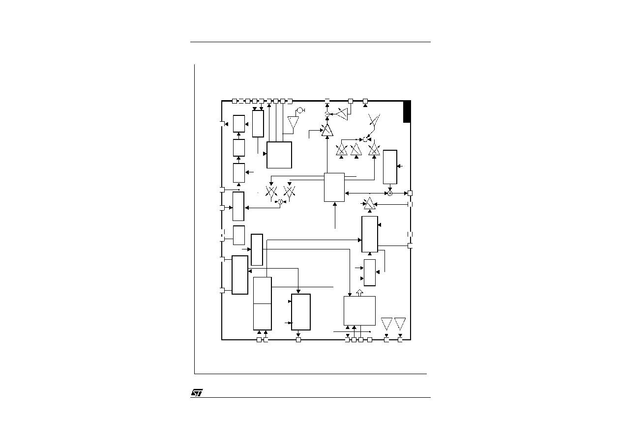
BLO
CK
DIAGRAM
HSize
7 bits
PLL1F
POSITION
R0 C0
HFLY
PLL2C
HOUT
7
8
6
5
12
4
26
Phase/Frequency
Comparator
H-Phase(7bits)
VCO
Phase
Comparator
Phase
Shifter
H-Duty
(7bits)
Hout
Buffer
Safety
Processor
Controller
SPin bal
7bits
x
2
x
Key bal
7bits
B+
Lock/Unlock
Identification
Sync
Processor
Sync Input
Select
(1bit)
VSYNC
HFLY
HorizontalMoire
Generator
7 bits+ON/OFF
+Frequency
Geometry
Tracking
VDFAMP
7bits
Internal
reference
(7bits)
5V
Amp
Symmetry
2x7bits
x
2
x
2
Corner
7bits
E/Wpcc
7bits
Keyst.
7 bits
x
DC
VerticalMoire
Cancel
7bits+ON/OFF
STV6886
VSYNC
VPOS
7bits
VAMP
7bits
7 bits
7 bits
Vertical
Oscillator
Ramp Generator
S and C
Correction
I
2
C Interface
H
ref
V
ref
11
19
17
29
25
28
16
14
15
HGND
VGND
VCC
XRAY
+OUT
ISENSE
COMP
REGIN
GND
10
9
24
FOCUS
HFOCUS-
EWOUT
23
18
20
22
V
OUT
VBREATH
V
AGCCAP
V
CAP
21
13
32
27
30
31
1
2
3
H/HVIN
V
SYNCIN
HMOIRE
/HLOCK
SDA
SCL
GND
5V
HREF
VREF
CAP
x
4
x
2
+