STV8203
MULTISTANDARD TV SOUND DEMODULATOR
January 1999
PRELIMINARY DATA
.
PERFORMS FM MONO, FM 2 CARRIERS
AND NICAM RECEPTION
.
B/D/G/H/I/K/K1/K2/L/L'
.
UP TO 500kHz DEVIATION FM DEMODULATOR
.
ALL PRE AND POST-PROCESSING INTE-
GRATED FILTERS, ALIGNMENT FREE
.
STANDARD RECOGNITION FLAG
.
SINGLE QUARTZ CRYSTAL
.
I
2
C BUS CONTROLLED
.
AM AND DOUBLE SCART AUDIO MATRIX
.
STAND-BY WITH THRU MODE
.
SINGLE BIT DACS
.
EASY IMPLEMENTATION OF AUTOSTAN-
DARD MODE
.
ADVANCED OPERATING MODE FOR FULL
CUSTOMIZATION
.
SIF AGC WITH WIDE RANGE
This is advance information on a new product now in development or undergoing evaluatio n. Details are subject to change without notice.
DESCRIPTION
The STV8203 provides all the necessary circuitry
for demodulation of all Nicam and German stereo
audio transmission. It is very suitable for TV appli-
cations as well as for VCR, Personal Computer or
Set Top Box applications. Different transmission
standardsare automaticallydetected and demodu-
lated without user intervention. The recovered
audio signals can be made available in analog
form. More, the STV8203 integrates an audio ma-
trix with a THRU mode when the IC is in stand-by.
Very flexible applications are possible thanks to
smart I
2
C program modes and large choice of
appropriate audio processing ICs.
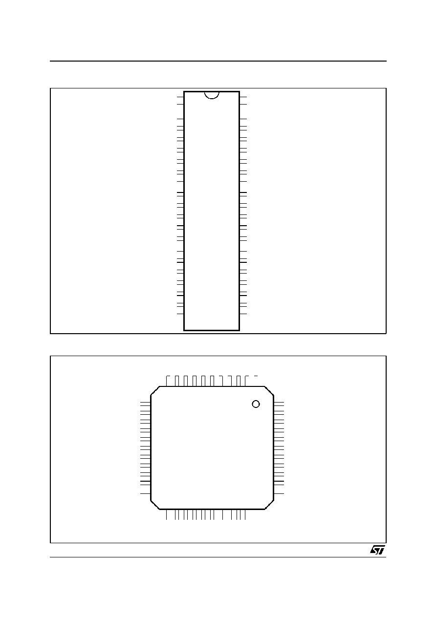
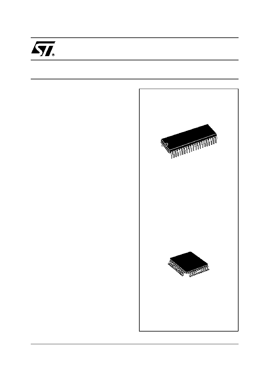
SHRINK42
(Plastic Package)
ORDER CODE : STV8203
TQFP44 (10 x 10 x 1.4mm)
(Full Plastic Quad Flat Pack)
ORDER CODE : STV8203D
1/31

PIN LIST
Pin Number
Name
Type
Function
SDIP42
TQFP44
1
7
CAP5
Analog
Decoupling for ADC Supply Regulator Output
2
8
SIF1
Analog
Subcarrier 1 Input
3
9
CAP6
Analog
Decoupling for Input Amplifier Reference
4
10
SIF2
Analog
Subcarrier 2 Input
5
11
GND3
Power
Ground for Input Amplifier
6
12
MOUT
Analog
Mono Audio Output
7
13
MIN
Analog
Mono Audio Input
8
14
CAP8
Analog
ADC Vtop Decoupling
9
15
LIL1
Analog
Line 1 Left Input (SCART 1)
10
16
LIR1
Analog
Line 1 Right Input (SCART 1)
11
17
GND4
Power
Audio Ground
12
18
LIL2
Analog
Line 2 Left Input (SCART 2)
13
19
LIR2
Analog
Line 2 Right Input (SCART 2)
14
20
CAP2
Analog
Decoupling for Audio Matrix
15
21
CAP1
Analog
Decoupling for Bandgap Reference
16
22
AOL1
Analog
Line 1 Left Output (SCART 1)
17
23
AOR1
Analog
Line 1 Right Output (SCART 1)
18
24
CAP4
Analog
Audio Matrix V
DD
(5V)
19
25
AOL2
Analog
Line 2 Left Output (SCART 2)
20
26
AOR2
Analog
Line 2 Right Output (SCART 2)
-
27
NC
-
Not Connected
21
28
AV
CC
Power
Audio Matrix Supply
22
29
CAP7
Analog
Decoupling for Digital Regulator Output
23
30
RESET
Input
Power On Reset
24
31
NC
-
Not Connected
25
32
NC
-
Not Connected
26
33
NC
-
Not Connected
27
34
NC
-
Not Connected
28
35
NC
-
Not Connected
29
36
NC
-
Not Connected
30
37
NC
-
Not Connected
31
38
NC
-
Not Connected
32
39
GND1
Power
Digital Ground
33
40
XOUT
Analog
Crystal Oscillator Output
34
41
XIN
Analog
Crystal Oscillator Input
35
42
Not used
Input
To be connected to ground
36
43
SDA
Bi-directional
I
2
C Serial Data
37
44
SCL
Input
I
2
C Serial Clock
-
1
NC
-
Not Connected
38
2
NC
-
Not Connected
39
3
CAP3
Analog
Decoupling for Digital 3V (regulator output)
40
4
REG
Analog
Base Drive for External Regulator Transistor
41
5
DV
DD5
Power
5V Supply
42
6
GND2
Power
Digital Ground
82
03-
01.
T
B
L
STV8203
3/31
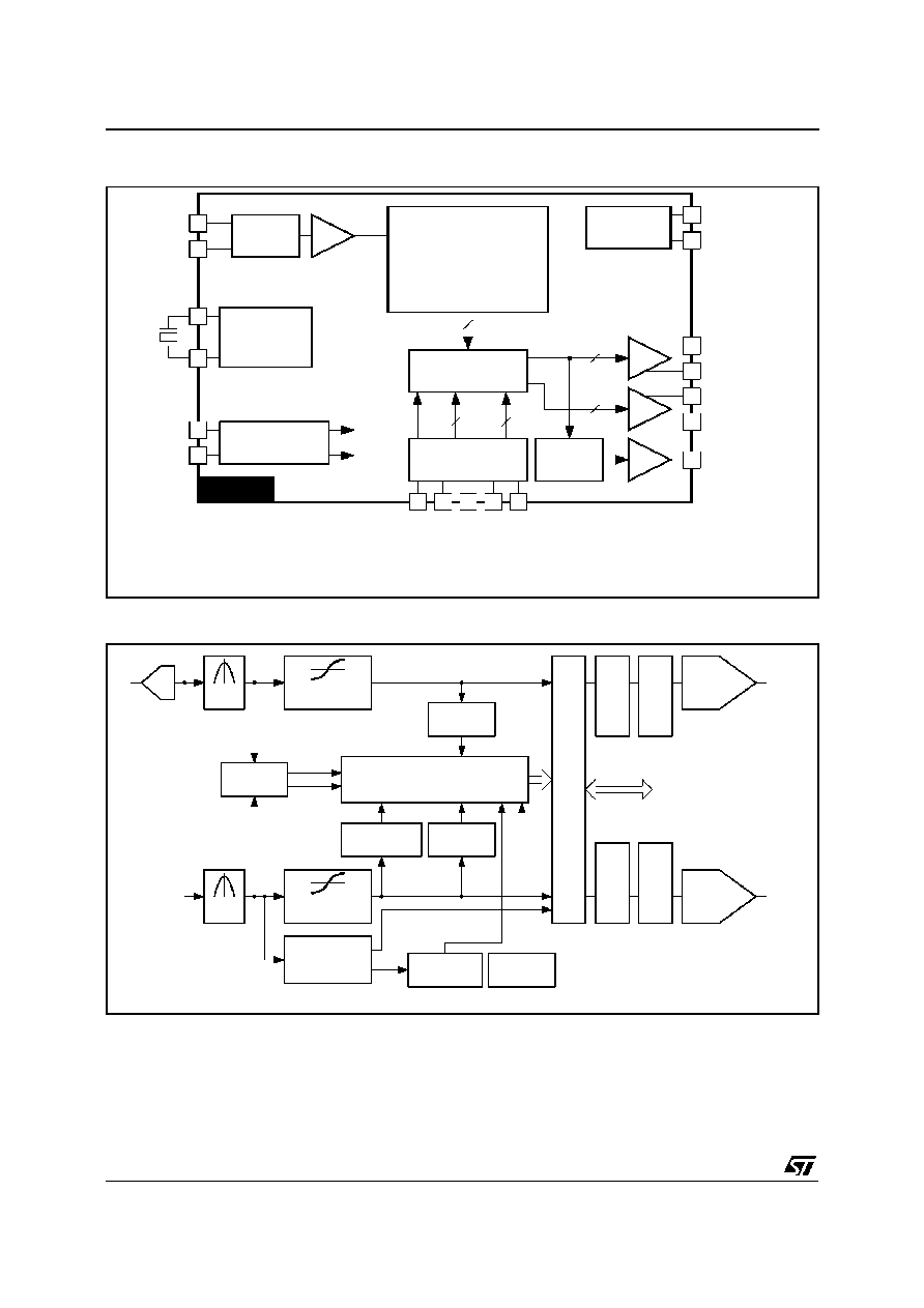
FUNCTIONAL DESCRIPTION
As can be seen from the block diagram, the input to
the demodulator section is selectable from one of
two I.F. sources via the I
2
C bus. The selected signal
is then passed through an AGC block, having a
range of 28dB, before being digitised in the
ADC unit. A single quartz crystal (suggested value :
between 24.712MHzand 27MHz) is used for the all
thedigital processing, including demodulation,iden-
tification, control, filtering. This has the advantage
of a singleclock signalsource for the whole IC which
eliminates problems of multiple clock. The single
clock can be chosen to minimize interference in the
TV IF and RF stages of the tuner system.
The demodulatorsystem can identify and demodu-
late all the standarddescribedin the Table1. There-
sult of the recognition is flagged up to the host
system via the I
2
C bus communication system.
In the case of NICAM transmissions, in the event
of a failure of the received signal or a degradation
of the bit error rate (BER) below a prescribed level,
the system will automatically default to the reserve
sound transmission on mono FM or AM.
For FM demodulation, the discriminator can nor-
mallyhandle signals having 250kHz deviation. This
covers all European standards, and ensure an
optimized compromise for the signal to noise ratio
in one hand, and overmodulation in the other hand.
However, it is possible to extand the deviation
range up to 500kHz (I
2
C programmable) in order to
cover requests of some broadcasters.
Fully automatic standard recognition and setting
can be achieve using simple routines.
Appropriate de-emphasis networks in the digital
domain are applied to the resulting demodulated
signals (50
µ
s, J17), followed by dematrixing if re-
quired. The digital datastream is then passed
through 2 x 16bits DACs before the audio matrix.
All this first section is working at 3.3V thanks to an
integrated voltage regulator. In stand-by mode, the
voltage regulator pulls the voltage down to zero,
ensuring no power dissipation in this part.
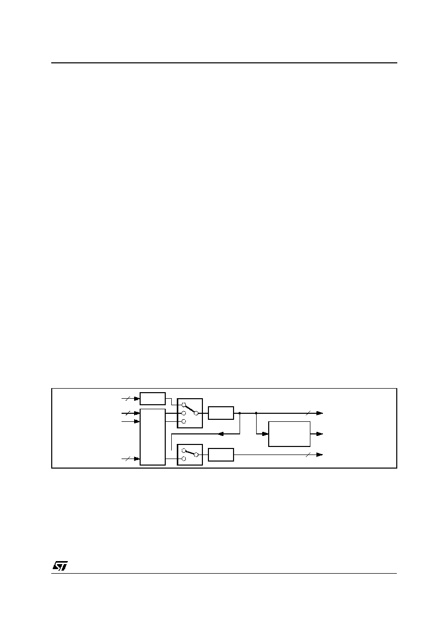
An audio matrix allows the selection of inputs ap-
plied on the outputsSCART1, SCART2 and MONO
according to the diagram shown in Figure 1.
The "MOUT" outputs either the signal L1, or R1 or
(L1+R1)/2. This allows to record the selected chan-
nel in mono mode, for example on the linear chan-
nel of a VCR simultanously with the stereo mode.
Maximum output swing is 1V
RMS
.
The audio matrix section has its own power supply
regulator, allowing to keep this part working even
when the rest is in stand-by mode. This achieves a
"THRU" mode from input "SCART1" to output
"SCART2" andinput"SCART2" to output"SCART1".
The maximum output swing of both SCART1 and
SCART2 is 2V
RMS
.
Remark : Circuit operation is possible with only a
single 5V supply. In this case, the AV
CC
supply pin
is connected to 5V. Maximum output swing is then
limited to 1V
RMS
and a 6dB attenuationis automat-
ically added to the DAC output. In that case, the
resistor shown as R2 = 39
in the Application Dia-
gram (between Pin 8 and Pin 21) must be replace
by a short circuit to avoid clipping.
MUTE
MUTE
L1, R1,
(L1 + R1)/2
SELECTOR
MOUT
AO1(SCART1)
MUTE
DAC
MIN
LI1(SCART1)
2
2
2
2
2
S1
S2
GAIN
±
6dB
LI2(SCART2)
AO2(SCART2)
L1/R1
L2/R2
82
03-
05
.
E
P
S
Figure 1 : Audio Matrix
STV8203
5/31