1
2
3
5
6
7
10
11
14
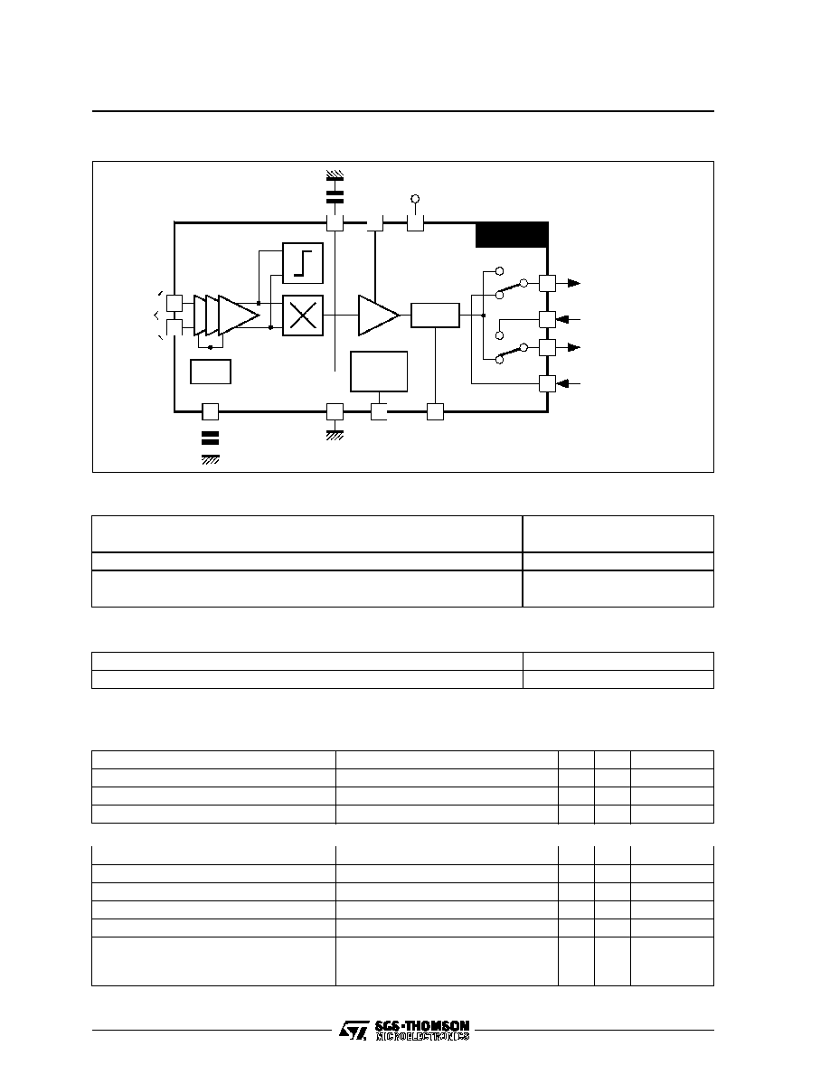
AGC
Capacitor
Switching
Input
Mute
Input
IF INPUT
AGC
4
12
13
V
CC
Level
Switch
Mean
Capacitor
MUTE
LOGIC
CONT
SW1
A
B
SW2
C
A
9
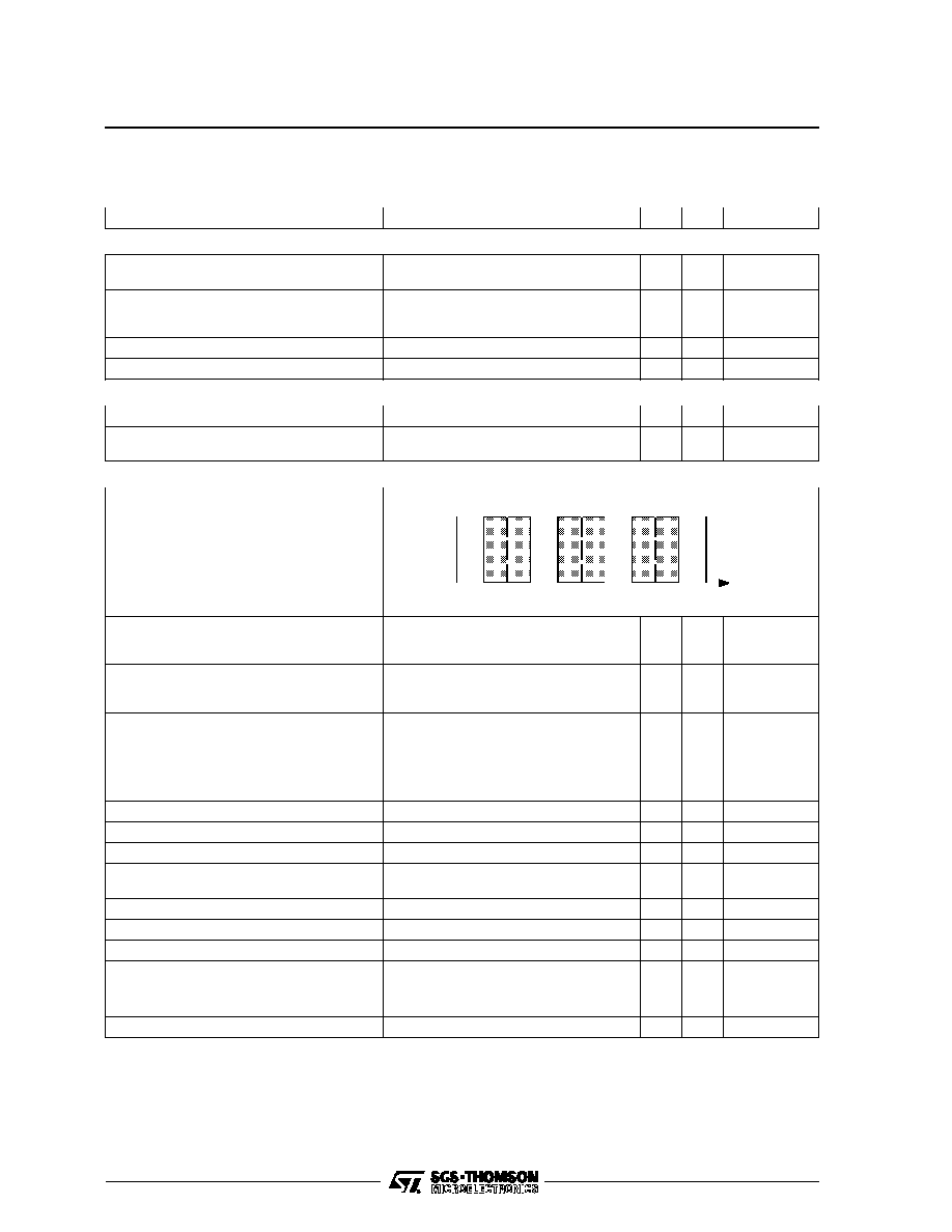
Main Sound Output
FM Sound Input
External Sound Output
External Sound Input
STV8225
8225-02.EPS
BLOCK DIAGRAM
ABSOLUTE MAXIMUM RATINGS
Symbol
Parameter
Value
Unit
V
CC
Supply Voltage
13
V
T
stg
Storage Temperature
-40, +150
o
C
T
oper
Operating Temperature
0, +70
o
C
P
tot
Power Dissipation
0.35
W
8225-01.TBL
THERMAL DATA
Symbol
Parameter
Value
Unit
R
th (j-a)
Junction-ambient Thermal Resistance
Max.
90
o
C/W
8225-02.TBL
ELECTRICAL CHARACTERISTICS (V
CC
= 9V, V
IN
= 10mV
RMS
, f
SC
= 32.4MHz, f
M
= 1kHz,
m = 54% modulation depth, Audio BW = 40Hz to 15kHz, T
amb
= 25
o
C, unless otherwise specified)
Symbol
Parameter
Test Conditions
Min.
Typ. Max.
Unit
V
CC
Supply Voltage
Pin 12
8
9
10
V
I
CC
Supply Current
Pin 12
20
30
mA
Supply Voltage Rejection
Pins 9, 7, 12 - V
Ripple
= 0.5V
PP
, f = 100Hz
45
53
dB
IF AMPLIFIER
Ri 1, 14
Input Resistance (Pins 1-14)
Resistance between Pin 1 and 14
2
k
Ci 1, 14
Input Capacitance (Pins 1-14)
Capacitance between Pin 1 and 14
2
pF
VIF min
Minimum IF Input Signal
IF input signal for V
OUT
= V
NOM
- 3dB
70
µ
V
RMS
VIF max
Maximum IF Input Signal
IF input signal for V
OUT
= V
NOM
+ 1dB
75
mV
RMS
DAV
AGC Range
DAV = VIF max / VIF min
61
dB
l
AGC
Maximum AGC Output Current
(Pin 2)
Charging and discharging
±
35
±
50
±
65
µ
A
IF Bandwidth
-3dB
50
MHz
8225-03.TBL
STV8225
2/6
ELECTRICAL CHARACTERISTICS (continued) (V
CC
= 9V, V
IN
= 10mV
RMS
, f
SC
= 32.4MHz, f
M
= 1kHz,
m = 54% modulation depth, Audio BW = 40Hz to 15kHz, T
amb
= 25
o
C, unless otherwise specified)
Symbol
Parameter
Test Conditions
Min.
Typ. Max.
Unit
AM DEMODULATOR
AF Output Voltage (Pins 7-9)
Level switch (Pin 4) open
Level switch (Pin 4) connected to GND
200
400
250
500
300
600
mV
RMS
mV
RMS
AF Bandwidth (Pins 7-9)
Lower Limit
Upper Limit
-3dB versus nominal signal
50
40
Hz
kHz
Harmonic Distorsion (Pins 7-9)
THD + Noise
0.7
1.8
%
S/N (Pins 7-9)
Weighted according to CCIR 468-4
55
dB
MUTE
Threshold Level (Pin 6)
Mute mode if voltage below threshold
0.2
0.3
0.4
V
Attenuation (Pins 7-9)
Level switch (Pin 4) connected to GND
TV - AM mode
80
96
dB
AUDIO SWITCHES
Switching Voltage (Pin 10)
Operation mode
View1
Level 1 (Pin 10)
For voltage below this level
TV-FM mode :
Pin 7 connected to A
Pin 9 connected to C
1.8
2.3
2.6
V
View2
Level 2 (Pin 10)
For voltage below this level
TV-AM mode :
Pin 7 connected to A
Pin 9 connected to A
4.1
4.6
4.9
V
View3
Level 3 (Pin 10)
For voltage below this level
AV-AM mode :
Pin 7 connected to B
Pin 9 connected to A
For voltage above this level
AV-FM mode :
Pin 7 connected to B
Pin 9 connected to C
6.4
6.8
7.2
V
Input Current (Pin 10)
Source current
0.3
2
µ
A
Input Dynamic Range (Pins 5-11)
2
V
RMS
Input Resistance (Pins 5-11)
35
50
k
Switch Gain
V
IN
= 2V
RMS
, f = 1kHz
Pin 7 vs Pin 11 and Pin 9 vs Pin 5
-0.6
-0.1
0.4
dB
Crosstalk
f = 1kHz
70
85
dB
Output Resistance (Pins 7-9)
70
100
130
Output Current Source (Pins 7-9)
1
mA
Switch Distorsion
V
IN
= 2V
RMS
, f = 1kHz, THD + Noise,
Pin 7 vs Pin 11 and Pin 9 vs Pin 5
0.1
0.5
%
Output Noise
Unweighted
7
20
µ
Vp
DC Plop at AF Output Pin
10
50
mV
8225-04.TBL
TV
FM
Viev1
TV
AM
Viev2
AV
AM
Viev3
AV
FM
0V
V
CC
V
10
8225-03.EPS
STV8225
3/6