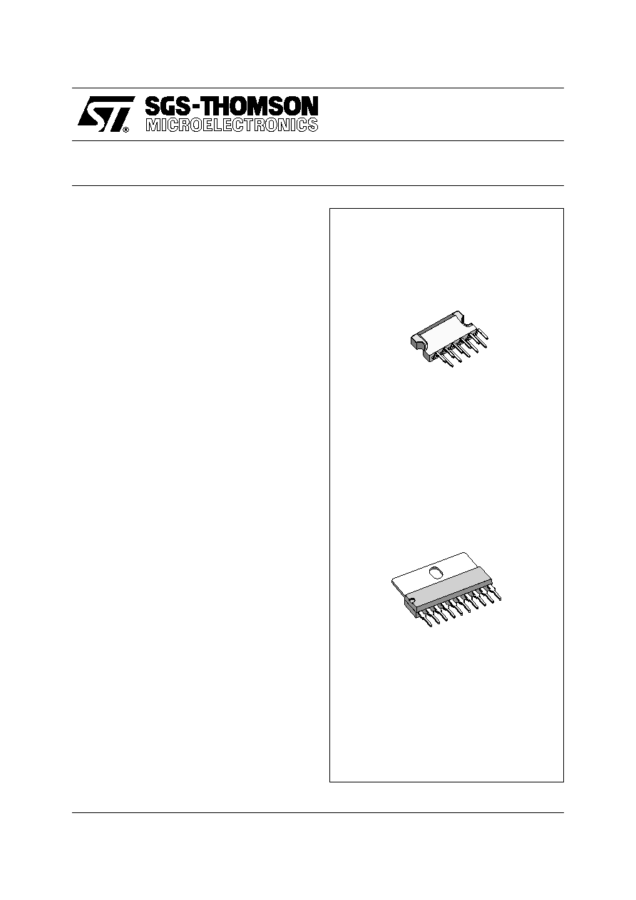
STV9303
PULSE DRIVEN VERTICAL BOOSTER
September 1993
ADVANCE DATA
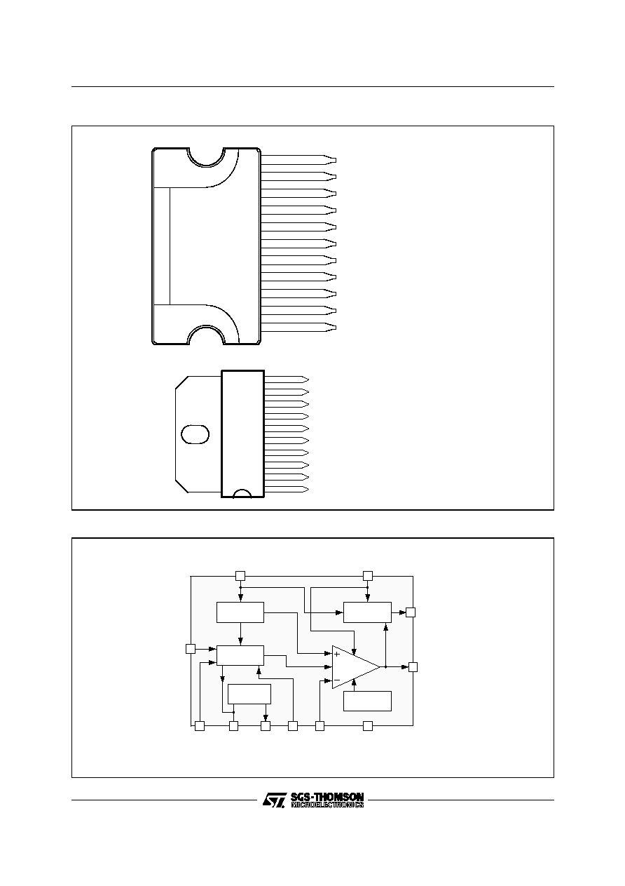
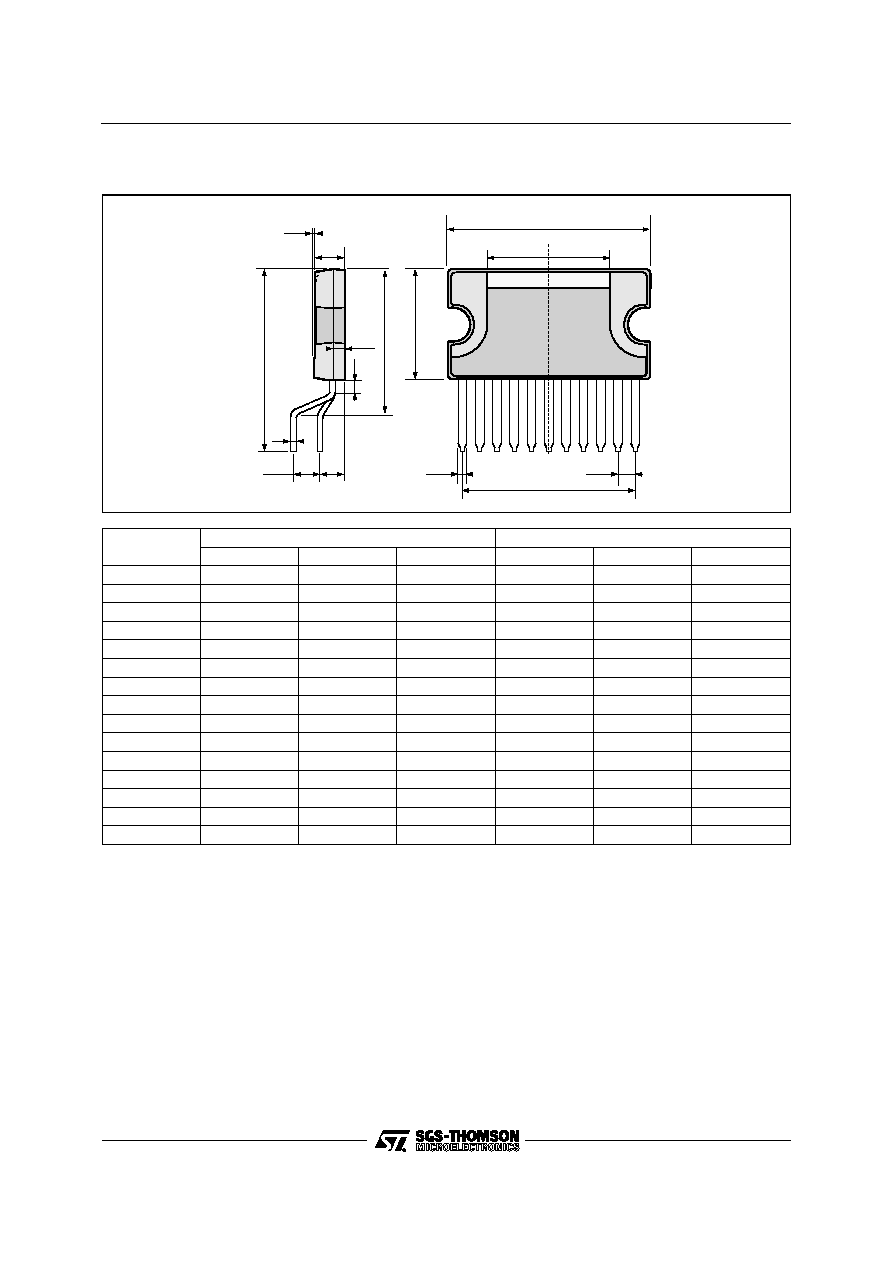
CLIPWATT 11
(Plastic Package)
ORDER CODE : STV9303W
This is advance information on a new product now in development or undergoing evaluation. Details are subject to change without notice.
.
OUTPUT CURRENT UP TO 2.5App
.
70V MAXIMUM FLYBACK VOLTAGE
.
INTERNAL FLYBACK GENERATOR
.
INTERNAL REFERENCE VOLTAGE GENER-
ATOR
.
INTERNAL RAMP GENERATOR
.
SAWTOOTH STARTED BY THE END OF
SYNC PULSE OR BY AN INTERNAL
MONOSTABLE
.
THERMAL PROTECTION
DESCRIPTION
The STV9303 is a pulse driven vertical booster
intended for use in color TV. It includes a vertical
ramp generator specially designed to fit with deflec-
tion processors like STV2102 or STV2110 which
provide a 10.5 line lengh vertical pulse. The dis-
charging of the sawtooth capacitor is triggerred by
the trailing edge of the vertical sync and the charg-
ing by the leading edge.
During the sync pulse duration, the sawtooth will
remains at its bottom value. Another possibility is
to use the internal monostable (by connecting an
external capacitor on Pin 5) to define the point
where the sawtooth will restart. This second possi-
bility is very usefull to avoid interlacing problems
when using a conventional deflection processor
delivering a small duration vertical pulse.
The STV9303 includes a very efficient power am-
plifier for direct driving of a TV picture tube in B &
W or color television.
For power consumption saving, a flyback generator
is also included. The current and voltage capabili-
ties (2.5App max output current and 70V flyback
peak voltage), make this IC also suitable for large
screen TV sets.
Thermal protection is also provided.
SIP10
(Plastic Package)
ORDER CODE : STV9303
1/6

ABSOLUTE MAXIMUM RATINGS (CLIPWATT Pin Connections)
Symbol
Parameter
PIns
Value
Unit
V
S
Supply Voltage
10
35
V
V
F
, V
O
Flyback Voltage
1-2
70
V
V
I-
Amplifier Input Voltage
9
V
S
V
I
OP
Peak Output Current
1
1.5
A
I
11
Flyback DC Current at V
O
< V
S
11
100
mA
I
11
Flyback Peak Current (f = 50 or 60Hz, T
fly
< 1.5ms)
11
1.8
A
V
3
Trigger Input Voltage
3
V
S
V
T
stg
Storage Temperature
-40, +150
o
C
T
j
Junction Temperature
Internally limited
93
03
V
-
0
1
.
T
B
L
THERMAL DATA
Symbol
Parameter
Value
Unit
T
pt
Junction Temperature at Thermal Shutdown
Typ.
140
o
C
T
ph
Thermal Protection Hysteresis
Typ.
25
o
C
R
th (j-c)
Junction-case Thermal Resistance
CLIPWAT11
SIP10
Max.
Max.
3
10
o
C/W
o
C/W
93
03
V
-
0
2
.
T
B
L
ELECTRICAL CHARACTERISTICS (CLIPWATT Pin Connections)
(V
S
= 35V, T
amb
= 25
o
C, unless otherwise specified)
Symbol
Parameter
Test Conditions
Min.
Typ.
Max.
Unit
I
2
Pin 2 Quiescent Current
I
1
= 0, I
11
= 0
16
36
mA
I
10
Pin 10 Quiescent Current
I
1
= 0, I
11
= 0
15
30
mA
-I
7
Ramp Generator Bias Current
V
7
= 0
1
�
A
-I
7
Ramp Generator Current
V
7
= 0, -I
4
= 20
�
A
18.5
20
21.5
�
A
dI
7
/I
7
Ramp Generator Linearity
V
7
= 0 to 12V, -I
4
= 20
�
A
0.2
1
%
V
1L
Out Saturation Voltage to GND
I
1
= 0.1A
I
1
= 1.25A
0.1
1.2
1
2.0
V
V
V
1H
Out Saturation Voltage to V
S
-I
1
= 0.1A
-I
1
= 1.25A
0.9
1.6
1.6
3.0
V
V
V
4
Reference Voltage
-I
4
= 20
�
A
6.3
6.6
6.9
V
dV
4
/V
S
Reference Voltage Drift versus V
S
V
S
= 10V to 35V
1
2
mV/V
dV
4
/d
I4
Reference Voltage Drift versus I
4
I
4
= 10
�
A to 30
�
A
0.1
1
mV/
�
A
V
R
Internal Reference Voltage
4.15
4.40
4.65
V
V
D11-10
Diode Fwd Voltage
I
D
= 1.25A
1.5
3
V
V
D1-2
Diode Fwd Voltage
I
D
= 1.25A
1.5
3
V
G
V
Output Stage Open Loop Gain
f = 100Hz
70
dB
V
fs
V10-11 Saturation Voltage
-I
11
= 1.25A
1.5
3.0
V
V
11
Pin 11 Saturation Voltage
I
11
= 20mA
0.8
2
V
V
3
Trigger Input Threshold
2.6
3.0
3.4
V
V
8
Sawtooth Pedestall Voltage
1.85
V
I
1
Peak-to-peak Operating Current Range
0.4
2.5
A
V
7M
Max. Voltage on Pin 7
12
V
I
7
Min. Discharging Current
5
mA
K1
Delay between end of Sync Pulse and beginning
of Sawtooth versus value of Capacitor on Pin 5
100
�
s/nF
t
do
Max. Delay between end of Sync Pulse and
beginning of Sawtooth Capacitor charging
without Capacitor on Pin 5
2
10
�
s
93
03
V
-
0
3
.
T
B
L
STV9303
3/6
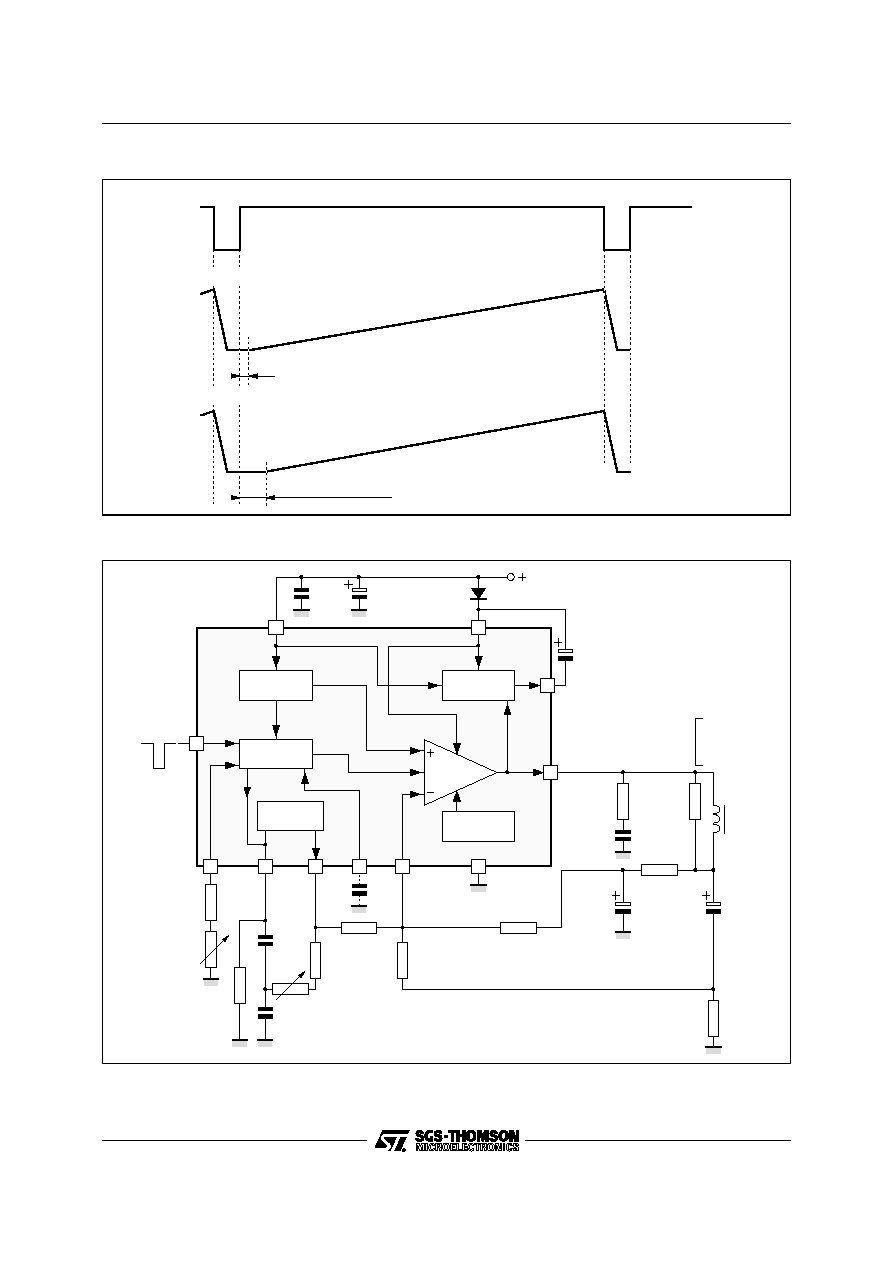
Sync Pulse (Pin 3)
Vertical Sawtooth on Pin 7 (Pin 5 NC with CLIPWATT or with SIP10)
Vertical Sawtooth on Pin 7 with Cd connected on Pin 5 (CLIPWATT only)
t
d
= (K1 . Cd) +
t
d o
t
d o
93
03
V
-
0
4
.
E
P
S
WAVEFORMS
THERMAL
PROTECTION
1
2
3
6
7
8
10
BUFFER
STAGE
V
S
VOLTAGE
REGULATOR
POWER
AMP
CLOCK
PULSE
FLYBACK
GENERATOR
9
4
11
0.1
�
F
1000
�
F
35V
1N4001
10 0
�
F
35V
180k
220k
1.5
330
0.22
�
F
2.7k
YOKE
1
1000
�
F
25V
TRIG. INP
RAMP
GENERATOR
5
= 30V
YOKE
Ry = 12.5
Ly = 25mH
Iy = 1.6App
10 0
�
F
25V
2.7k
2.2k
8.2k
56k
820
k
100k
100nF
100
nF
*
*
Cd optional to adjust sawtooth start delay
93
03
V
-
0
5
.
E
P
S
APPLICATION CIRCUIT (CLIPWATT)
STV9303
4/6