STV9306
BUS CONTROLLED VERTICAL DEFLECTION SYSTEM
WITH EAST/WEST CORRECTION OUTPUT CIRCUIT
December 1998
PRELIMINARY DATA
15
14
13
12
11
10
9
8
7
6
5
4
3
2
1
BREATHING
SENS1
EWFB
SENS2
EWOUT
VOPS
OUT
GND
FLYBACK
V
S
SYNC
CHOLD
SDA
CRAMP
SCL
9306
-
0
1.
E
P
S
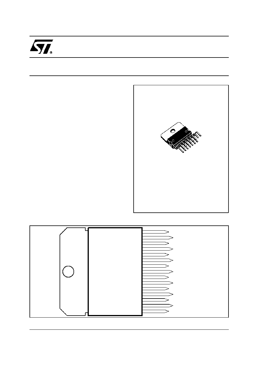
PIN CONNECTIONS
MULTIWATT15
(Plastic Package)
ORDER CODE : STV9306
.
FULLY I
2
C CONTROLLED
.
DMOS POWER HALF-BRIDGE AMPLIFIER
.
DC COUPLED OPERATION
.
INTERNAL FLYBACK GENERATOR (UP TO 60V)
.
SELF ADAPTED SAWTOOTH (50/60Hz)
.
100Hz OPERATION
.
VERTICAL LINEARITY, AMPLITUDE AND
CENTERING ADJUSTMENTS
.
HORIZONTAL
WIDTH,
PINCUSHION,
TRAPEZOID AND CORNER ADJUSTMENTS
.
BREATHING CORRECTION
.
4/3, 16/9 CRT APPLICATION
.
THERMALPROTECTION
.
LINEAR VERTICAL ZOOM FUNCTION
.
E/W CLASS A OUTPUT
.
LOW EXTERNAL COMPONENTS
This is advance information on a new product now in development or undergoing evaluatio n. Details are subject to change without notice.
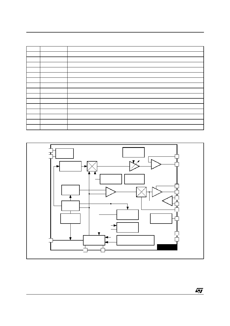
DESCRIPTION
The STV9306 is a fully I
2
C controlled vertical
deflection IC designed for use in 110
�
, 4/3 or 16/9
CRT applications. It integrates both the vertical
deflection and E/W correction circuitries neces-
sary in design of a 110
�
chassis.
1/12

ELECTRICAL CHARACTERISTICS
V
S
= 24V, R
SENS
= 0.5
, Normal mode, T
amb
= 25
o
C, unless otherwise specified
Symbol
Parameter
Test Conditions
Min.
Typ.
Max.
Unit
SUPPLY
V
S
Operating Supply Voltage
16
28
V
I
S
Supply Current on Pins 6-10
I
O
= 0
40
60
mA
RAMP GENERATOR CONTROL
V
Rlow
Minimum V
RAMP
Voltage at Pin 2
1.8
2
2.2
V
t
D
Discharge Time at Pin 2
50
�
s
I
ISY
Synchro Input Current at Pin 5
V
SY
= 0
-6
-3
�
A
V
THSY
Synchro Threshold Voltage at Pin 5
2.5
3
3.5
V
I
OB
Oversize Blank Input Current at Pin 5
70
100
�
A
POWER AMPLIFIER
I
IBR
Breathing Current Input Current at Pin 15
V
BREATH
= 0V
-10
-5
�
A
V
BREATH
Breathing Operating Voltage at Pin 15
0
9
V
V
7H
Saturation Voltage to supply at Pin 7
I
O
= -1.5A, V
9
> V
S
+ 5V
2.5
3.5
V
V
7L
Saturation Voltage to Ground at Pin 7
I
O
= 100mA
1.5
2.5
V
I
SENS1
I
SENS2
Bias Input Current at Pin 14
Bias Input Current at Pin 12
V
14
= 0V
V
12
= 0V
-20
-20
-10
-10
�
A
�
A
V
9H
Saturation Voltage to supply at Pin 9 versus Pin 10
I
O
= -1.5A
2.5
3.5
V
V
9L
Saturation Voltage to Ground at Pin 9
I
O
= 1.5A
1.5
2.5
V
dV
9H
/st
dV
9L
/dt
+10
+5
mV/
�
C
mV/
�
C
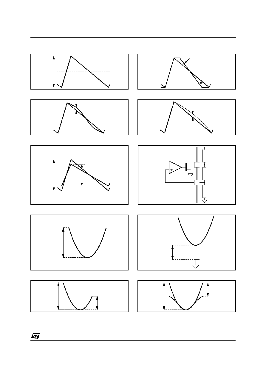
VERTICAL OUTPUT (Pin 9)
I
PP
Vertical Deflection Current (see Figure 1)
V_SAW = 000000
V_SAW = 111111
1.8
3
A
A
I
DC
Average Current (vertical shift)
at V_SAW = 111111
V_SH = 01111
V_SH = 11111
-0.35
0.35
A
A
Z
SLP
Z
SLP
=
slope in zoom mode
slope in normal mode
(see Figure 2)
V_ZOOM = 000
V_ZOOM = 111
106
130
%
%
I
SC
S Correction = I
SC
/I
PP
(see Figure 3)
V_SC = 0000
V_SC = 1111
0
6
%
%
I
CC
C Correction = I
CC
/I
PP
(see Figure 4)
V_CC = 0111
V_CC = 1111
-3
3
%
%
BR
Breathing BR =
I
PP
-
I
PPB
I
PP
(see Figure 5)
BR
Min.
V
15
= 9V
BR
Max.
V
15
= 1V
0
10
%
%
EAST/WEST CORRECTION (V_SAW = 100000, V_SH = 10000, V_SC = 0000, V_CC = 1000) (see Figure 6)
I
BIAS
Input Bias Current at Pin 13
-1
-0.5
�
A
V
PAR
Parabola Amplitude (pincushion correction)
at Pin 13 (see Figure 7)
EW_AMP = 00000
EW_AMP = 11111
0
5
V
V
V
DCEW
Horizontal Width Adjustment at Pin 13
(see Figure 8)
EW_DC = 00000
EW_DC = 11111
HShrink active
1
6
+6
V
V
V
Trap
Trapezium Correction at Pin 13 (see Figure 9)
Trap = V
PARTUP
/V
PARTLOW
EW_TRAP = 01111
EW_TRAP = 11111
0.6
1.7
Shape
Parabola Shape (corner correction) at Pin 13
(see Figure 10) - Shape = V
COR
/V
PAR
EW_SHAPE = 00000
EW_SHAPE = 11111
0
50
%
%
V
11L
Saturation Voltage
I
OUT
= 500mA
2
V
9
306-
04.
T
B
L
STV9306
4/12