 | –≠–ª–µ–∫—Ç—Ä–æ–Ω–Ω—ã–π –∫–æ–º–ø–æ–Ω–µ–Ω—Ç: STV9937 | –°–∫–∞—á–∞—Ç—å:  PDF PDF  ZIP ZIP |
DATASHEET
February 2004
1/49
STV9937
120-MHz On-Screen Display for Monitors including
PictureBooST
TM
and 4 True Independent Window Displays
Æ
Main Features
Horizontal frequency up to 150 kHz
I≤C interface for microcontrollers with slave
address BA(h) in Read and Write modes
PictureBoost
‰
Pixel clock (F
PIXEL1
) for the PictureBooST
‰
(PB) from 30 to 60 MHz synchronised either
on Hsync or on Hfly: CLK1
Window position programmable by RGB or
I
2
C interface
Video Analog inputs with comparator on
three channels
Three 8 bit registers for other data,
programmable by RGB
OSD
On-chip Pixel Clock Generator (F
PIXEL2
) from
7.68 MHz to 120 MHz, CLK2
OSD clock synchronized on Hsync or Hfly
Programmable horizontal resolutions from
384 to 1524 dots per scan line
4 independent windows all with character
display
Overlapping windows with automatic control
of display priorities and scrolling menu
effects
Independent and programmable displays,
positions and sizes for each window
Transparent or 8 programmable background
colors for each window
Window size up to 16 rows of 32 characters
Each window has its own bordering or
shadowing effects with programmable color,
height and width
Each window can be separately erased
Programmable common positioning to easily
control centered display
496 standard and 16 multi-color characters or
graphic fonts in ROM. Character fonts can be
customized using a mask-programmable
ROM
Characters
Common character height and row space.
Character height from 18 to 127 lines and
space lines from 0 to 62 split above and below
character rows
12 x 18 dot matrix per character
Display of up to 640 characters
Programmable shadow effects for characters
in each separate window
32 programmable background, foreground,
blinking character colors for characters (8
possibilities per window)
8 selectable colors for standard characters
Transparent and 8 selectable colors for
background
On-Screen Effects
Fade-in/Fade-out effects
Possibility of full-screen display with a
selectable color
PDIP 24 (Plastic Dual In line Shrink Package)
ORDER CODE: STV9937P/AA

STV9937
2/49
Chapter 1
General Description . . . . . . . . . . . . . . . . . . . . . . . . . . . . . . . . . . . . . . . . . . . . . . . .5
1.1
Pin Description ................................................................................................................... 7
Chapter 2
Register Addressing . . . . . . . . . . . . . . . . . . . . . . . . . . . . . . . . . . . . . . . . . . . . . . .9
2.1
I≤C Protocol .......................................................................................................................... 9
2.1.1
Data to Write .........................................................................................................................................................9
2.1.2
Transmission Formats ...........................................................................................................................................9
2.1.3
Format, Window and Row Address (FWR) .........................................................................................................10
2.1.4
Format, Attribute and Column Address (FAC) ....................................................................................................10
2.1.5
Control Data, Color Codes or Character Codes .................................................................................................11
2.1.6
Configuration of Transmission Formats .............................................................................................................11
2.2
Format Changing ............................................................................................................... 11
To change from Format A to Format B ...............................................................................................................11
To change from Format A to Format C ...............................................................................................................11
To change from Format B to Format A ...............................................................................................................11
To change from Format B to Format C ...............................................................................................................12
2.3
Read Mode ......................................................................................................................... 12
2.4
Addressing Map ................................................................................................................. 12
Chapter 3
Window Specifications . . . . . . . . . . . . . . . . . . . . . . . . . . . . . . . . . . . . . . . . . . . .13
3.1
Enable Display ................................................................................................................... 14
3.2
Origin Positions for the 4 Windows .................................................................................... 14
3.2.1
General Horizontal Delay (HD) ...........................................................................................................................14
3.2.2
General Vertical Delay (VD) ................................................................................................................................14
3.3
Window Positions in the Frame .......................................................................................... 15
3.3.1
Window Horizontal Delay ....................................................................................................................................15
3.3.2
Window Vertical Delay ........................................................................................................................................15
3.4
Window Size: Number of Character Rows and Character Columns .................................. 16
3.4.1
Window Horizontal Size ......................................................................................................................................16
3.4.2
Window Vertical Size ..........................................................................................................................................16
3.5
Window Background Color ................................................................................................. 17
3.6
Window Bordering and Shadowing Effects ........................................................................ 17
3.6.1
Enable Bordering or Shadowing Effects .............................................................................................................17
3.6.2
Bordering or Shadowing Selection .....................................................................................................................17
3.6.3
Border or Shadow Color .....................................................................................................................................18
3.6.4
Bordering or Shadowing Size .............................................................................................................................18
3.7
Window Display Priority Management ............................................................................... 19
Chapter 4
Character Specifications . . . . . . . . . . . . . . . . . . . . . . . . . . . . . . . . . . . . . . . . . . .20
4.1
General Description ........................................................................................................... 20
4.2
Horizontal Resolution ........................................................................................................ 20
4.3
Character Height ............................................................................................................... 20

3/49
STV9937
4.4
Space Lines ....................................................................................................................... 21
4.5
Character Colors ................................................................................................................ 22
4.5.1
Character Background Color ..............................................................................................................................22
4.5.2
Character Color ...................................................................................................................................................23
4.5.3
Character Blinking Effect ....................................................................................................................................24
4.6
Character Shadowing ......................................................................................................... 24
4.7
Character Font ................................................................................................................... 25
Chapter 5
RAM Specification . . . . . . . . . . . . . . . . . . . . . . . . . . . . . . . . . . . . . . . . . . . . . . . .26
5.1
Character Coding ............................................................................................................... 26
5.2
Window Memory Allocation ................................................................................................ 26
5.3
Memory Size Allocation ...................................................................................................... 26
5.4
Window Reset .................................................................................................................... 28
Chapter 6
Pixel Clock Generator . . . . . . . . . . . . . . . . . . . . . . . . . . . . . . . . . . . . . . . . . . . . .29
Chapter 7
Picture BooSTTM . . . . . . . . . . . . . . . . . . . . . . . . . . . . . . . . . . . . . . . . . . . . . . . . .30
7.1
Video RGB Input Stage ......................................................................................................30
7.2
PictureBooSTTM RGB Decoder ........................................................................................ 31
7.2.1
Data Sent Using I≤C ............................................................................................................................................31
7.2.2
Data Sent Using the RGB Channel ....................................................................................................................31
7.3
Control Registers Description ............................................................................................ 33
7.4
Line and Pixel Offsets ........................................................................................................ 34
7.5
PLL Synchronised .............................................................................................................. 34
Chapter 8
General OSD Programming . . . . . . . . . . . . . . . . . . . . . . . . . . . . . . . . . . . . . . . . .35
8.1
Enable OSD ....................................................................................................................... 35
8.2
Fade-in and Fade-out Effect .............................................................................................. 35
8.3
Full Screen Display ............................................................................................................ 35
8.4
Signal Polarity and Triggering ........................................................................................... 36
Vertical Sync Triggering (VS input) .....................................................................................................................36
Horizontal Sync Triggering (HSYNC input) .........................................................................................................36
RGB Output Polarity (ROUT, GOUT and BOUT outputs) ...................................................................................36
Fast Blanking Output Polarity (FBLK output) ......................................................................................................37
8.5
Reset .................................................................................................................................. 37
Power On Reset .................................................................................................................................................37
Soft Reset ...........................................................................................................................................................37
PLL Register Reset .............................................................................................................................................37
Chapter 9
Registers . . . . . . . . . . . . . . . . . . . . . . . . . . . . . . . . . . . . . . . . . . . . . . . . . . . . . . . .38

STV9937
4/49
9.1
Register Specification ........................................................................................................ 38
Chapter 10
Application Hints . . . . . . . . . . . . . . . . . . . . . . . . . . . . . . . . . . . . . . . . . . . . . . . . .42
10.1
Software Hints .................................................................................................................... 42
10.1.1
Programming Recommendations .......................................................................................................................42
10.1.2
Examples of Programming ..................................................................................................................................42
Hard reset at power-up (following a power-up) ...................................................................................................42
Change of position & size of 1 window (ex. window 3) without disable of window .............................................42
Re-allocation, reset, and writing new characters in windows ..............................................................................43
10.2
Hardware Hints .................................................................................................................. 43
Chapter 11
Application Diagrams . . . . . . . . . . . . . . . . . . . . . . . . . . . . . . . . . . . . . . . . . . . . .44
Chapter 12
Electrical and Timing Characteristics . . . . . . . . . . . . . . . . . . . . . . . . . . . . . . . .45
12.1
Absolute Maximum Ratings ............................................................................................... 45
12.2
Operating Conditions ......................................................................................................... 45
12.3
Electrical and Timing Characteristics ................................................................................. 45
12.4
I≤C Bus Characteristics ...................................................................................................... 46
Chapter 13
Package Mechanical Data . . . . . . . . . . . . . . . . . . . . . . . . . . . . . . . . . . . . . . . . .47
Chapter 14
Revision History . . . . . . . . . . . . . . . . . . . . . . . . . . . . . . . . . . . . . . . . . . . . . . . . . .48
5/49
STV9937
General Description
1
General Description
The STV9937 is an Advanced On Screen Display generator for CRT monitors. It includes a specific
architecture allowing multiple menu displays, a built in 512 character ROM and the Picture
BooST
TM
system.
The patented Picture BooST
TM
feature allows images to be boosted either within a window, a
screen area or even over the entire screen.
Using traditional architecture (OSD + Preamp STV9212) and without any additional devices on the
CRT board, Picture BooST
TM
boosts the brightness and sharpness of the video on CRT displays
giving a TV like effect.
The STV9937 can drive Picture BooST
TM
either through the VGA cable (using RGB or DDC),
through the USB channel via the MCU or through the OSD menu (the registers can be accessed by
the MCU via I≤C).
The STV9937 embeds the RGB data decoder, the Picture BooST
TM
Control Registers and the
Picture BooST
TM
signal generator.
Along with the Picture BooST
TM
and traditional OSD features, the STV9937 allows a simultaneous
display of up to four menus anywhere on the screen. Each of the four independent windows, all
displaying characters, can be overlapped and display priorities are automatically controlled.
Window sizes and positions are independently programmable as well as scrolling menu effects.
Programming of the general OSD and of the 4 windows is controlled by an I≤C bus in Read and
Write modes, to suit the various CRT displays.
Associated with an easily programmable character height, the internal PLL generates the
programmable pixel clock, without using a crystal oscillator, that defines the character width
making the device suitable for multi-sync applications.
A maximum of 640 characters, defined in the mask-programmable ROM, are distributed among
the 4 windows and displayed simultaneously.
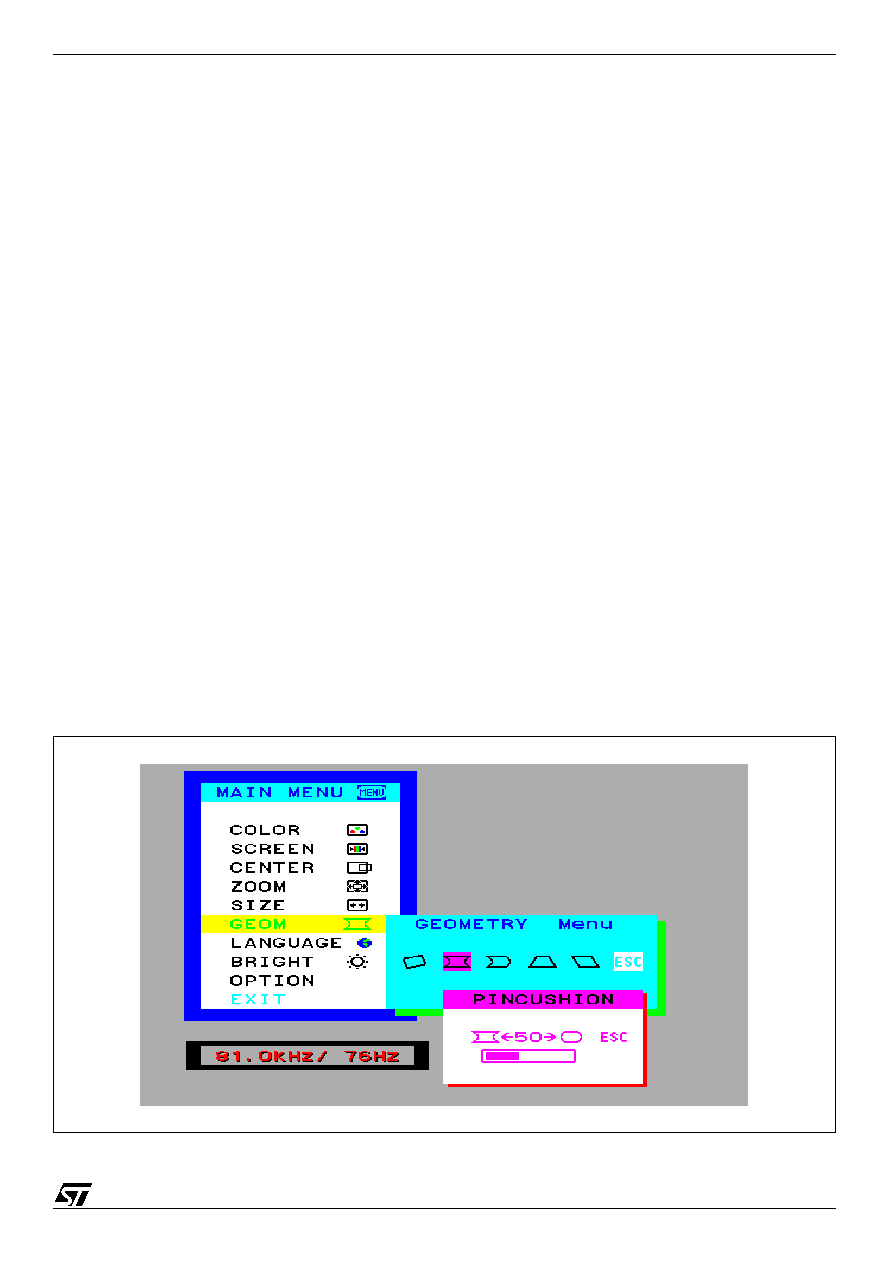
Figure 1: Multi-window Concept with Character Display