
1/49
TDA7406T
April 2001
Audio processor:
s
4 STEREO INPUTS
s
4 MONO INPUTS
s
VOLUME CONTROL
s
7 BAND EQUALIZER FILTER CONTROL
s
HIGH PASS FILTER FOR SUBWOOFER
APPLICATION
s
DIRECT MUTE AND SOFT MUTE
s
INTERNAL BEEP GENERATION
s
4 INDEPENDENT SPEAKER OUTPUTS
s
SOFT STEP SPEAKER CONTROL
s
SUBWOOFER OUTPUT
s
7 BAND SPECTRUM ANALYZER
s
FULL MIXING CAPABILITY
s
PAUSE DETECTOR
Stereo decoder:
s
RDS MUTE
s
NO EXTERNAL ADJUSTMENTS
s
AM/FM NOISEBLANKER WITH SEVERAL
TRIGGER CONTROLS
s
PROGRAMMABLE MULTIPATH DETECTOR
s
QUALITY DETECTOR OUTPUT
Digital control:
s
I
2
C-BUS INTERFACE
DESCRIPTION
The device includes a high performance audio pro-
cessor with 7 bands equalizer and spectrum analyzer
plus a stereo decoder-noiseblanker. The whole low
frequency signal processing necessary for state-of-
the-art as well as future car radios is therefore provid-
ed. The digital control allows a full programming not
only of the audioprocessor and filter characteristics
but also in the stereodecoder part especially for the
adaptation to different IF-devices.
TQFP44
ORDERING NUMBER: TDA7406T
CAR RADIO SIGNAL PROCESSOR
PIN CONNECTION (Top view)
TDA7406T
2/49
SUPPLY
THERMAL DATA
ABSOLUTE MAXIMUM RATINGS
ESD:
All pins are protected against ESD according to the MIL883 standard.
Symbol
Parameter
Test Conditions
Min.
Typ.
Max.
Unit
V
S
Supply Voltage
7.5
9
10
V
I
S
Supply Current
V
S
= 9V
42
60
78
mA
SVRR
Ripple Rejection @ 1kHz
Audioprocessor (all Filters flat)
60
dB
Stereodecoder + Audioprocessor
55
dB
Symbol
Description
Value
Unit
R
th j-pins
Thermal Resistance Junction-pins max
65
�C/W
Symbol
Parameter
Value
Unit
V
S
Operating Supply Voltage
10.5
1 V
T
amb
Operating Temperature Range
-40 to 85
�C
T
stg
Storage Temperature Range
-55 to +150
�C
3/49
TDA7406T
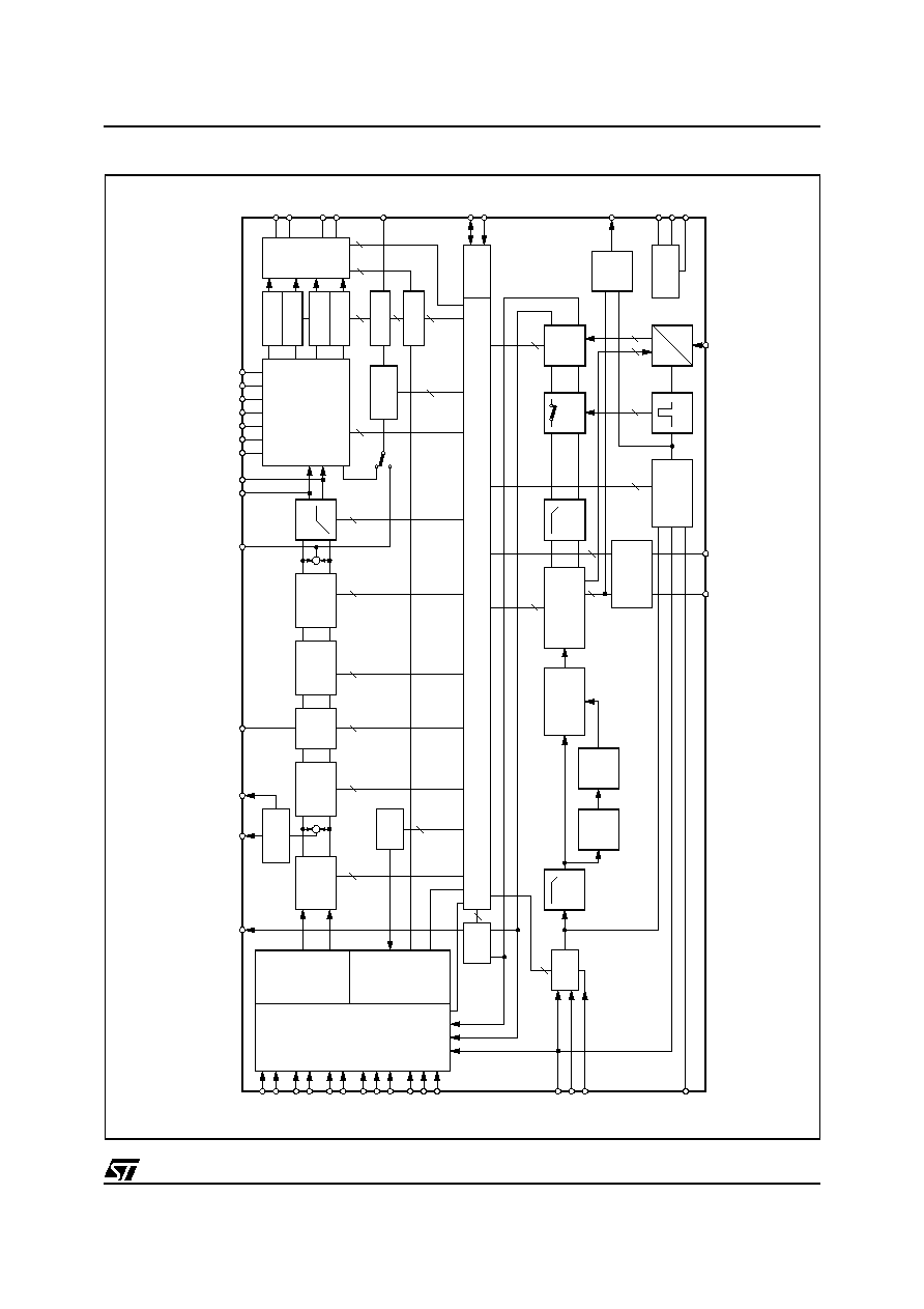
BLOCK DIAGRAM
SUPPLY
CREF
OUT LF
MIXINLF
MIXINLR
MIXINRF
MIXINRR
ACINR
ACINL
SWIN
ACOUTR
ACOUTL
SWACOUT
D01AU1255
I
2
C BUS
BEEP
PAUSE
V
S
MDR
INPUT
MULTIPLEXER
AM/MPX2
MPIN
MPOUT
MPX1
CMPX
AM IF
LOUDNESS
SPECTRUM
ANALYSER
SOFT
MUTE
SOFTSTEP
VOLUME
HIGH
PASS
7 BAND
EQUALIZER
ACIN
SUBWOOFEROUT
OUTPUT
SELECTOR
OUT RF
OUT SW
SDA
SCL
QUA
DIGITAL CONTROL
CDR
MDL
TAPEL
GND
SM
SAOUT
MAIN
SOURCE
SELECTOR
L
L
R
L
R
R
L
R
MIXING
SELECTOR
CDL
CD
MD
TAPE
CDC
TAPER
PDL+
PD-
PDR+
PHONE
TIM
NAVI
PHONE
TIM
NAVI
AM
FM
DCIN
FRONT
REAR
SOFT STEP
FADER
SOFT STEP
FADER
MIXER
IN-GAIN +
AUTO ZERO
SUBWOOFER
FILTER
STD
INGAIN
PILOT-
CANCELLATION
MULTIPATH
DETECTOR
AM/FM
NOISE BLANKER
DEMODULATOR
+ STEREO ADJUST
+ STEREO BLED
+
+
80KHz-LP
PLL
PILDET
25KHz-LP
OUT RF
OUT RR
SOFT STEP
FADER
SOFT STEP
FADER
SOFT STEP
FADER
MONO
FADER
S & H
QUAL
PULSE
FORMER
HIGH
CUT
D
A
SACLK
PAUSE
LEVEL

TDA7406T
4/49
1
AUDIOPROCESSOR PART
Features:
s
Input multiplexer
� Pseudo differential CDC stereo input, programmable as single-ended input.
� 3 single-ended stereo inputs.
� 4single-ended mono inputs.
� Input gain adjust 0...15dB in 1dB steps.
� Internal offset-cancellation (autozero).
s
Beep
� Internal beep generator with 4 different frequencies.
s
Mixing stage
� Beep, Phone- and Navi-Input mixable to all speaker outputs.
� TIM or tuner (FM/AM) programmable as fourth mixing source.
� Level control range of 95dB (+15...-79db).
s
Loudness
� Loudness programmable center frequency and filter slope.
� 0...19dB attenuation in 1dB steps.
� selectable flat-mode (constant attenuation).
s
Volume
� Gain/Attenuation with 0.5dB step resolution.
� soft-step control with programmable blend times.
� 110dB range (+32...-79db).
s
Equalizer
� Seven bands equalizer with 2
nd
order frequency response switch-capacitors filters.
� Center frequency programmable for lowest and highest filter.
� Programmable quality factor in four steps for each filter.
� �15dB range with 1dB steps.
s
Spectrum analyzer
� seven bandpass 2
nd
order frequency response switch-capacitors filters
� Programmable quality factor for different visual appearance
� Analog output
� Controlled by external serial clock
s
High pass Filter
� 2nd order Butterworth high pass with programmable cut-off frequency
� Selectable flat-mode
s
Speakers
� 4 independent speaker controls with separate mute.
� Control range 95dB (+15...-79dB) in 1dB steps with soft step.
� 4 independent programmable mix inputs with 50% mixing ratio
s
Subwoofer
� Single-ended monaural output
� control range 95dB (+15...-79dB) in 1dB steps with soft step.
� separate mute
s
Mute functions
� direct mute
� digitally controlled Soft mute with 4 programmable mute-time

5/49
TDA7406T
Table 1. ELECTRICAL CHARACTERISTICS
(V
S
=9V; T
amb
=25�C; R
L
=10k
; all gains=0dB; f=1kHz; unless otherwise specified)
Symbol
Parameter
Test Condition
Min.
Typ.
Max.
Unit
INPUT SELECTOR
R
in
Input Resistance
all single ended Inputs
70
100
130
k
V
CL
Clipping Level
2.2
2.6
V
RMS
S
IN
Input Separation
80
100
dB
G
IN MIN
Min. Input Gain
-1
0
1
dB
G
IN MAX
Max. Input Gain
13
15
17
dB
G
STEP
Step Resolution
0.5
1
1.5
dB
V
DC
DC Steps
Adjacent Gain Steps
-5
1
5
mV
G
MIN
to G
MAX
-10
61
10
mV
V
offset
Remaining offset with Autozero
0.5
mV
DIFFERENTIAL STEREO INPUTS
R
in
Input Resistance (see Fig. 1)
Differential
70
100
130
k
CMRR
Common Mode Rejection Ratio
V
CM
= 1V
RMS
@ 1kHz
46
70
dB
V
CM
= 1V
RMS
@ 10kHz
46
60
dB
e
NO
Output-Noise @ Speaker-Outputs 20Hz - 20kHz, flat; all stages 0dB
11
�V
BEEP CONTROL
V
RMS
Beep Level
Mix-Gain = 6dB
250
350
500
mV
f
Beep
Beep Frequency
f
Beep1
475
500
525
Hz
f
Beep2
740
780
820
Hz
f
Beep3
1.48
1.56
1.64
kHz
f
Beep4
2.28
2.4
2.52
kHz
MIXING CONTROL
M
LEVEL
Mixing Ratio
Main / Mix-Source
-6/-6
dB
G
MAX
Max. Gain
13
15
17
dB
A
MAX
Max. Attenuation
-83
-79
-75
dB
A
STEP
Attenuation Step
0.5
1
1.5
dB
LOUDNESS CONTROL
A
STEP
Step Resolution
0.5
1
1.5
dB
A
MAX
Max. Attenuation
-21
-19
-17
dB
f
Peak
Peak Frequency
f
P1
180
200
220
Hz
f
P2
360
400
440
Hz
f
P3
540
600
660
Hz
f
P4
720
800
880
Hz
VOLUME CONTROL
G
MAX
Max. Gain
30
32
34
dB