
TEA3717
April 1993
STEPPER MOTOR DRIVER
.
HALF-STEP AND FULL-STEP MODE
.
BIPOLAR DRIVE OF STEPPER MOTOR FOR
MAXIMUM MOTOR PERFORMANCE
.
BUILT-IN PROTECTION DIODES
.
WIDE RANGE OF CURRENT CONTROL 5 TO
1000 mA
.
WIDE VOLTAGE RANGE 10 TO 45 V
.
DESIGNED FOR UNSTABILIZED MOTOR
SUPPLY VOLTAGE
.
CURRENT LEVELS CAN BE SELECTED IN
STEPS OR VARIED CONTINUOUSLY
DESCRIPTION
The TEA3717 is a bipolar monolithic integrated cir-
cuit intended to control and drive the current in one
winding of a bipolar stepper motor. The circuit con-
sists of an LS-TTL compatible logic input, a current
sensor, a monostable and an output stage with built-
in protection diodes. Two TEA3717 and a few exter-
nal components form a complete control and drive
unit for LS-TTL or microprocessor-controlled step-
per motor systems.
PIN CONNECTION (top view)
POWERDIP 12 + 2 + 2
ORDER CODE : TEA3717DP
1/8

ABSOLUTE MAXIMUM RATINGS
Symbol
Parameter
Value
Unit
V
mm
Power Supply Voltage (pins 14, 3)
45
V
V
CC
Logic Supply Voltage (pin 6)
7
V
V
in
V
in
V
V
Input Voltage
Logic Inputs
Analog Inputs
Reference Input
� 0.5 to 6
V
CC
15
V
I
in
I
in
Input Current
Logic Inputs
Analog Inputs
� 10
� 10
mA
I
O
Output Current
�
1
A
T
j
Junction Temperature
+ 150
�
C
T
stg
Storage Temperature Range
� 55 to + 150
�
C
T
oper
Operating Ambiant Temperature Range
0 to + 70
�
C
THERMAL DATA
Symbol
Parameter
Value
Unit
R
th (j-c)
Maximum Junction-pins Thermal Resistance
11
�
C/W
R
th (j-a)
Maximum Junction-ambient Thermal Resistance
45*
�
C/W
* Soldered on a 35 mm thick 20 cm
3
PC board copper area
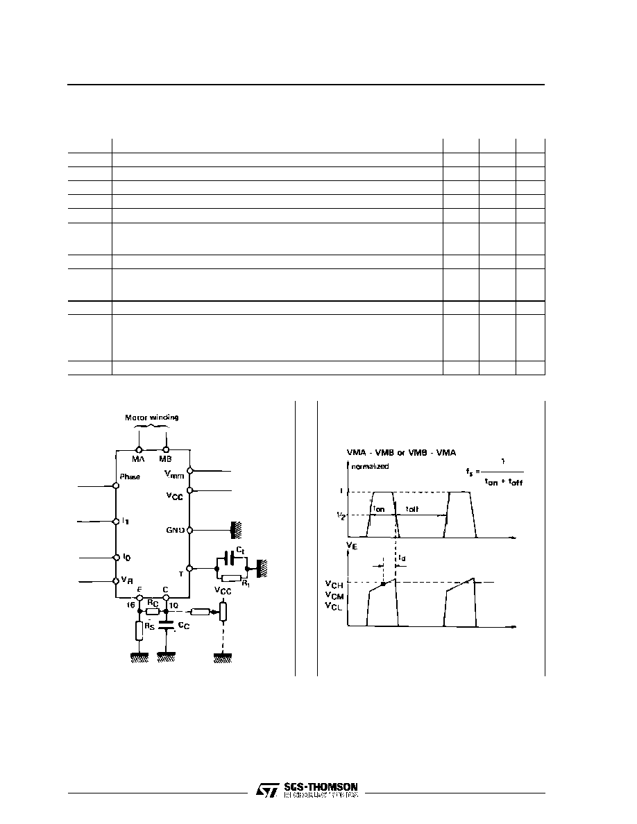
SCHEMATIC DIAGRAM
RECOMMENDED OPERATING CONDITIONS
Symbol
Parameter
Min.
Typ.
Max.
Unit
V
CC
Supply Voltage
4.75
5
5.25
V
V
mm
Supply Voltage
10
�
40
V
I
o
Output Current
0.020
�
0.8
A
T
amb
Ambient Temperature
0
�
70
�
C
t
r
Rise Time, Logic Inputs
�
�
2
�
s
t
f
Fall Time, Logic Inputs
�
�
2
�
s
TEA3717
2/8
ELECTRICAL CHARACTERISTICS
V
CC
= 5V,
�
5%, V
mm
= + 10V to + 40V, T
amb
= 0
o
C to + 70
o
C (unless otherwise specified)
Symbol
Parameter
Min.
Typ.
Max.
Unit
I
CC
Supply Current
�
�
25
mA
V
IH
High Level Input Voltage - Logic Inputs
2.0
�
�
V
V
IL
Low Level Input Voltage - Logic Inputs
�
�
0.8
V
I
IH
High Level Input Current - Logic Input (V
I
= + 2.4V)
�
�
20
�
A
I
IL
Low Level Input Current - Logic Inputs (V
I
= + 0.4V)
� 0.4
�
�
mA
V
CH
V
CM
V
CL
Comparator Threshold Voltage (V
R
= + 5.0V),
I
0
= 0, I
1
= 0
I
0
= 1, I
1
= 0
I
0
= 0, I
1
= 1
390
230
65
420
250
80
440
270
90
mV
I
CO
Comparator Input Current
� 20
�
20
�
A
I
off
Output Leakage Current (I
0
= 1, I
1
= 1)
T
amb
= + 25
�
C
T
amb
= + 70
�
C, V
S
= 40V, V
SS
= 5V
�
�
�
100
100
200
�
A
V
sat
Total Saturation Voltage Drop (I
o
= 500mA)
�
�
4.0
V
P
tot
Total Power Dissipation
I
o
= 500mA, f
s
= 30kHz
I
o
= 800mA, f
s
= 30kHz
�
�
1.8
3.7
2.3
�
W
t
off
Cut off Time (see figure 1 and 2, V
mm
= + 10V, t
on
5
�
s)
25
30
35
�
s
t
d
Turn off Delay (see figure 1 and 2, T
amb
= + 25
�
C, dVC/dt
50mV/
�
s)
�
1.6
�
s
Figure 2.
Figure 1 (see note)
TEA3717
3/8
FUNCTIONAL DESCRIPTION
The circuit is intented to drive a bipolar constant cur-
rent through one motor winding. The constant cur-
rent is generated through switch mode regulation.
Thereis a choice of three differentcurrent levels with
the two logic inputs l
0
and l
1
. The current can also
be switched off completely.
INPUT LOGIC
If any of the logic inputs is left open, the circuit will
treat it as a high level input.
I
0
I
1
Current Level
H
L
H
L
H
H
L
L
No Current
Low Current
Medium Current
Maximum Current
PHASE
-
This input determines the direction of cur-
rent flow in the winding, depending on the motor
connections. The signal is fed through a Schmidt-
trigger for noise immunity, and through a time delay
in order to guarantee that no short-circuit occurs in
the output stage during phase-shift. High level on
the PHASE-input causes the motor current flow
from M
A
through the winding to M
B
.
l
0
and l
1
-
The current level in the motor winding is
selected with these inputs. The values of the differ-
ent current levels are determined by the reference
voltage V
R
togetherwith the value of the sensing re-
sistor R
S
.
CURRENT SENSOR
This part contains a current sensing resistor (R
S
), a
low pass filter (R
C
, C
C
) and three comparators. Only
one comparator is active at a time. It is activated by
the input logic according to the current level chosen
with signals l
0
and l
1
. The motor current flows
through the sensing resistor R
S
. When the current
has increased so that the voltage across R
S
be-
comes higher than the reference voltage on the
other comparator input, the comparator output goes
high, which triggers the pulse generator and its out-
put goes high during a fixed pulse time (t
off
), thus
switching off the power feed to the motor winding,
and causing the motor current to decrease during
t
off.
SINGLE-PULSE GENERATOR
The pulse generator is a monostable triggered on
the positive going edge of the comparator output.
The monostableoutputis high duringthe pulse time,
t
off
, which is determined by the timing components
R
t
and C
t
.
t
off
= 0.69
R
t
C
t
The single pulse switches off the power feed to the
motor winding, causing the winding current to de-
crease during t
off
.
If a new trigger signal should occur during t
off
, it is
ignored.
OUTPUT STAGE
The output stage contains four Darlington transis-
tors and four diodes, connected in an H-bridge. The
two sinking transistors are used to switch the pow-
ersupplied to the motor winding, thus driving a con-
stant current through the winding.
It should be noted however, that it is not permitted
to short circuit the outputs.
V
CC
, V
mm
, V
R
The circuit will stand any order of turn-on or turn-off
of the supply voltages V
SS
and V
S
. Normal dV/dt
values are then assumed.
Preferably,V
R
shouldbe tracking V
CC
during power-
on and power-off.
ANALOG CONTROL
The current levels can be varied continuously either
if V
R
is varied or with a circuit varying the voltage fed
into the comparator terminal (see fig.1).
Note : R
S
= 1
, inductance free
R
C
= 1 k
C
C
= 820 pF, ceramic
R
t
= 56 k
C
t
= 820 pF, ceramic
TEA3717
4/8
