TEA7610
LOW-DROP VOLTAGE REGULATOR
June 1992
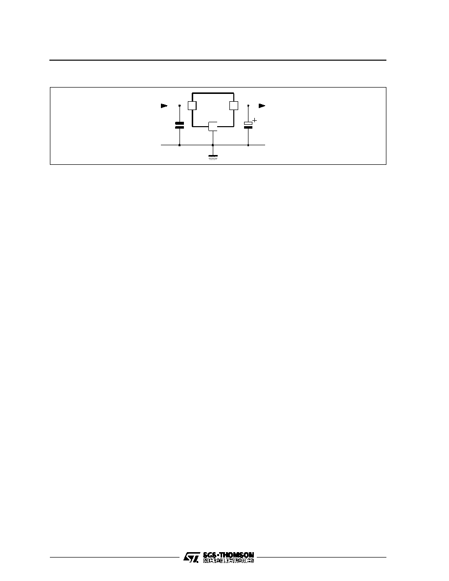
CURRENT
LIMIT
REGULATION
BALLAST
START-UP
BLOCK
THERMAL
PROTECTION
1
3
2
GND
V
I N
V
OU T
7610-02.EPS
BLOCK DIAGRAM
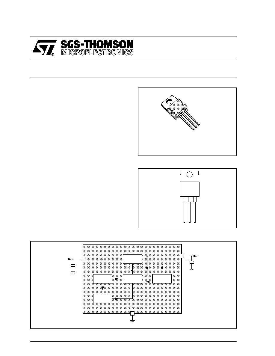
TO220
(Plastic Package)
ORDER CODE : TEA7610SP
s
V
O
= 10V
±
4 % (I
O
= 5mA)
s
I
O
= 5 TO 500mA
s
V
I
≠ V
O
= 0.6 V (I
O
= 500mA)
s
V
I (surge)
=
±
80V
s
THERMAL AND SHORT-CIRCUIT
PROTECTION
DESCRIPTION
TEA7610 is a low-drop regulator well suited to
supplying stabilized voltage to
µ
Ps in harsh indus-
trial environment.
Special care was taken to keep :
- Lowest possible output capacitor (1
µ
F).
1
2
3
1
2
3
=
=
= GND
V
V
I
O
GND
7610-01.EPS
PIN CONNECTIONS
1/4
ABSOLUTE MAXIMUM RATINGS
Symbol
Parameter
Value
Unit
V
I
Input Voltage
- Continuous
-
= 300 ms
30
80
V
V
V
I(R)
Reverse Input Voltage
- Continuous
-
= 120 ms
≠ 18
≠ 80
V
V
T
J
Operating Junction Temperature
≠ 45, +150
∞
C
T
stg
Storage Temperature
≠ 55, +150
∞
C
7610-01.TBL
THERMAL DATA
Symbol
Parameter
Value
Unit
R
th (j-c)
Junction-case Thermal Resistance
Max.
3
∞
C/W
R
th (j-a)
Junction-ambient Thermal Resistance
Max.
70
∞
C/W
7610-02.TBL
ELECTRICAL OPERATING CHARACTERISTICS
T
j
= 25
o
C, V
I
= 14.4V (unless otherwise specified) Output Capacitor = 10
µ
F (see note)
Symbol
Parameter
Min.
Typ.
Max.
Unit
V
O
Output Voltage (I
O
= 5 to 500mA)
9.7
10
10.3
V
V
I
Input Supply Voltage (permanent)
28
V
I
CC
Current Consumption
I
O
= 0mA
I
O
= 150mA
I
O
= 500mA
1.5
10
75
2
20
100
mA
mA
mA
K
VI
Line Regulation (V
I
= 11 to 26V ; I
O
= 5mA)
5
20
mV
K
VO
Load Regulation (I
O
= 5 to 500mA)
40
80
mV
V
I
- V
O
Drop-out Voltage
I
O
= 150mA
I
O
= 500mA
0.18
0.4
0.6
V
V
SVR
Supply Voltage Rejection
(I
O
= 350mA, f = 120Hz, C
O
= 1
µ
F, V
I
= 12
±
5V)
60
dB
I
OS
Short-circuit Output Current
0.5
0.7
A
7610-03.TBL
NOTE : Applications Hints
The output capacitor has a direct influence on output voltage stability. A 10
µ
F capacitor will provide satisfactory results. There is no upper limit
on this capacitor value.
If necessary, this value can be reduced down to 1
µ
F ; however, in such case, it should be checked that output capacitor keeps sufficiently high
capacitance and low equivalent series resistance in the whole temperature range.
Such low capacitor value is not recommended either, if output current is to switch abruptly from very high to very low values (for instance, 400
mA to < 1 mA).
ELECTRICAL OPERATING CHARACTERISTICS
T
j
= ≠ 45
o
C to +125
o
C, V
I
= 14 .4V (unless otherwise specified) Output Capacitor = 10
µ
F
Symbol
Parameter
Min.
Typ.
Max.
Unit
V
O
Output Voltage (I
O
= 5 to 500mA)
9.6
10
10.4
V
d
VO
d
t
Output Voltage Drift
T
j
= ≠ 45 to +25
∞
C
T
j
= + 25 to +125
∞
C
≠ 1
≠ 1.2
mV/
∞
C
I
CC
Current Consumption
I
O
= 0mA
I
O
= 150mA
I
O
= 500mA
2.5
25
120
mA
mA
mA
K
VI
Line Regulation (V
I
= 11 to 26V, I
O
= 5mA)
30
mV
K
VO
Load Regulation (I
O
= 5 to 500mA)
100
mV
V
I
- V
O
Drop-out Voltage
I
O
= 150mA
I
O
= 500mA
0.2
0.8
V
V
I
OS
Short-circuit Output Current
0.4
A
I
OM
Maximum Output Current
0.5
A
7610-04.TBL
TEA7610
2/4

L2
L3
A
C
D
E
D1
H3
F
G
L5
L7
L6
Dia.
H2
F2
PM-TO220.EPS
PACKAGE MECHANICAL DATA
3 PINS - PLASTIC TO220
Dimensions
Millimeters
Inches
Min.
Typ.
Max.
Min.
Typ.
Max.
A
4.8
0.189
C
1.37
0.054
D
2.4
2.8
0.094
0.110
D1
1.2
1.35
0.047
0.053
E
0.35
0.55
0.014
0.022
F
0.8
1.05
0.031
0.041
F2
1.15
1.4
0.045
0.055
G
4.95
5.08
5.21
0.195
0.200
0.205
H2
10.4
0.409
H3
10.05
10.4
0.396
0.409
L2
16.2
0.638
L3
26.3
26.7
27.1
1.035
1.051
1.067
L5
2.6
3
0.102
0.118
L6
15.1
15.8
0.594
0.622
L7
6
6.6
0.236
0.260
Dia.
3.65
3.85
0.144
0.152
TO220.TBL
Information furnished is believed to be accurate and reliable. However, SGS-THOMSON Microelectronics assumes no responsibility
for the consequences of use of such information nor for any infringement of patents or other rights of third parties which may result
from its use. No licence is granted by implication or otherwise under any patent or patent rights of SGS-THOMSON Microelectronics.
Specifications mentioned in this publication are subject to change without notice. This publication supersedes and replaces all
information previously supplied. SGS-THOMSON Microelectronics products are not authorized for use as critical components in life
support devices or systems without express written approval of SGS-THOMSON Microelectronics.
©
1994 SGS-THOMSON Microelectronics - All Rights Reserved
Purchase of I
2
C Components of SGS-THOMSON Microelectronics, conveys a license under the Philips
I
2
C Patent. Rights to use these components in a I
2
C system, is granted provided that the system conforms to
the I
2
C Standard Specifications as defined by Philips.
SGS-THOMSON Microelectronics GROUP OF COMPANIES
Australia - Brazil - China - France - Germany - Hong Kong - Italy - Japan - Korea - Malaysia - Malta - Morocco
The Netherlands - Singapore - Spain - Sweden - Switzerland - Taiwan - Thailand - United Kingdom - U.S.A.
TEA7610
4/4