Äîêóìåíòàöèÿ è îïèñàíèÿ www.docs.chipfind.ru
1/9
Application Specific Discretes
A.S.D
.
TM
THBTxxx11D
®
n
BIDIRECTIONAL CROWBAR PROTECTION
BETWEEN TIP AND GND, RING AND GND
AND BETWEEN TIP AND RING.
n
PEAK PULSE CURRENT :
I
PP
= 30A for 10/1000
µ
s surge.
n
HOLDING CURRENT :
I
H
= 150mA.
n
AVAILABLE IN SO8 PACKAGES.
n
LOW DYNAMIC BREAKOVER VOLTAGE.
FEATURES
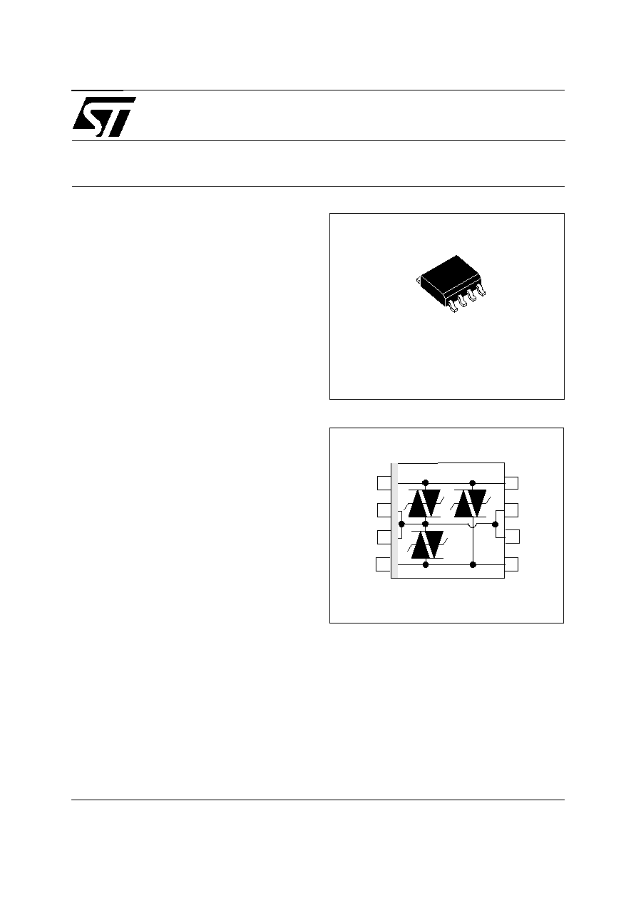
SO-8
Dedicated
to
telecommunication
equipment
protection,
these
devices
provide
a
triple
bidirectional protection function.
They ensure the same protection capability with
the same breakdown voltage both in longitudinal
mode and transversal mode.
A particular attention has been given to the internal
wire bonding. The "4-point" configuration ensures
a reliable protection, eliminating overvoltages
introduced by the parasitic inductances of the
wiring (Ldi/dt), especially for very fast transient
overvoltages.
Dynamic characteristics have been defined for
several types of surges, in order to meet the SLIC
maximum ratings.
DESCRIPTION
SCHEMATIC DIAGRAM
TRIPOLAR OVERVOLTAGE
PROTECTION FOR TELECOM LINE
October 2003 - Ed: 7A
TR-NWT-001089:
10/1000
µ
s
1000V
2/10
µ
s
2500V
(first level)
2/10
µ
s
5000V
(second level)
with line series resistors of 56
COMPLIES WITH BELLCORE STANDARDS :
2
GND
3
GND
1
TIP
4
RING
7
GND
6
GND
8
TIP
5
RING
TM: ASD is trademarks of STMicroelectronics.
THBTxxx11D
2/9
Symbol
Parameter
Value
Unit
I
PP
Peak pulse current (see note 1)
10/1000
µ
s
30
A
I
TSM
Non repetitive surge peak on-state current
(F=50Hz)
tp = 10 ms
t = 1s
8
3.5
A
T
stg
T
j
Storage temperature range
Maximum operating junction temperature
- 40 to + 150
+ 150
°C
°C
T
L
Maximum lead temperature for soldering during 10s
260
°C
ABSOLUTE MAXIMUM RATINGS (T
amb
= 25
°
C)
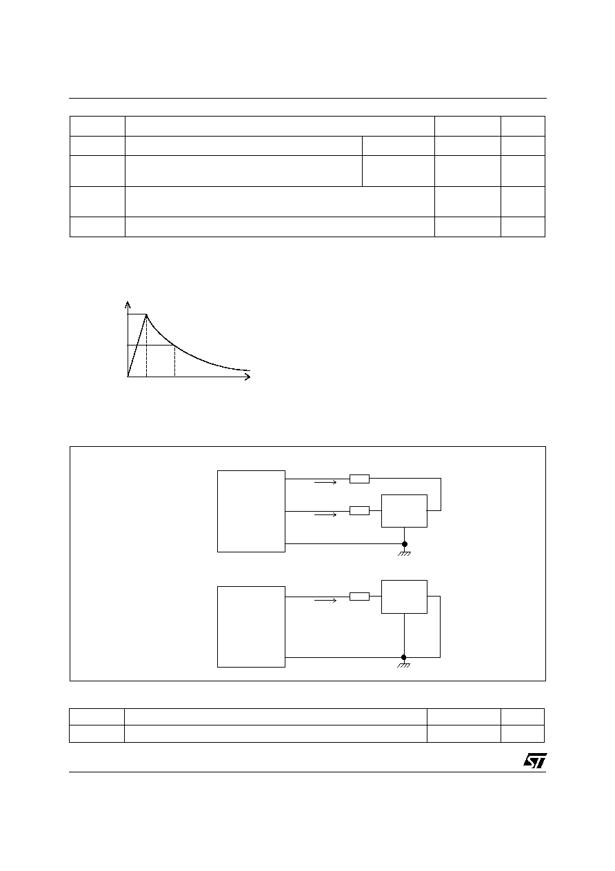
Note 1 : Pulse waveform :
10/1000
µ
s t
r
=10
µ
s
t
p
=1000
µ
s
100
50
% I
PP
t
t
r
p
0
t
TEST CIRCUITS FOR I
PP
Longitudinal mode
THBT
See test
circuit 3
R
P
TIP
RING
GND
I
PP
/2
RP
I
PP
/2
Transversal mode
TIP or
RING
GND
THBT
R
P
I
PP
See test
circuit 3
Symbol
Parameter
Value
Unit
R
th (j-a)
Junction to ambient
170
°
C/W
THERMAL RESISTANCES
THBTxxx11D
3/9
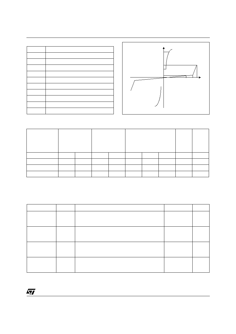
V
I
I
H
I
BO
V
RM
V
BR
BO
V
PP
I
R
I
Symbol
Parameter
V
RM
Stand-off voltage
I
RM
Leakage current at stand-off voltage
V
R
Continuous Reverse voltage
V
BR
Breakdown voltage
V
BO
Breakover voltage
I
H
Holding current
I
BO
Breakover current
V
F
Forward voltage drop
I
PP
Peak pulse current
C
Capacitance
ELECTRICAL CHARACTERISTICS (T
amb
= 25°C)
Type
I
RM
@ V
RM
I
R
@ V
R
V
BO
@
I
BO
I
H
C
max.
max.
note 1
max.
note 2
min.
max.
min
note 3
max
note 4
µ
A
V
µ
A
V
V
mA
mA
mA
pF
THBT15011D
5
135
50
150
210
50
400
150
80
THBT16011D
5
135
50
160
230
50
400
150
80
THBT20011D
5
180
50
200
290
50
400
150
80
THBT27011D
5
240
50
270
380
50
400
150
80
Note 1:
I
R
mesuared at V
R
guarantees V
BR
> V
R
Note 2:
Measured at 50 Hz (1 cycle) test circuit 1.
Note 3:
See the reference test circuit 2.
Note 4:
V
R
= 1V, F = 1MHz.
STATIC PARAMETERS
Type
Symbol
Test conditions (see note 5)
Maximum
Unit
THBT15011D
V
BO
10/700
µ
s
1.5kV
R
p
=10
I
PP
=30A
1.2/50
µ
s
1.5kV
R
p
=10
I
PP
=30A
2/10
µ
s
2.5kV
R
p
=62
I
PP
=38A
190
190
200
V
THBT16011D
V
BO
10/700
µ
s
1.5kV
R
p
=10
I
PP
=30A
1.2/50
µ
s
1.5kV
R
p
=10
I
PP
=30A
2/10
µ
s
2.5kV
R
p
=62
I
PP
=38A
200
200
210
V
THBT20011D
V
BO
10/700
µ
s
1.5kV
R
p
=10
I
PP
=30A
1.2/50
µ
s
1.5kV
R
p
=10
I
PP
=30A
2/10
µ
s
2.5kV
R
p
=62
I
PP
=38A
270
270
280
V
THBT27011D
V
BO
10/700
µ
s
1.5kV
R
p
=10
I
PP
=30A
1.2/50
µ
s
1.5kV
R
p
=10
I
PP
=30A
2/10
µ
s
2.5kV
R
p
=62
I
PP
=38A
360
360
400
V
Note 5 :
See test circuit 3 for V
BO
dynamic parameters; R
p
is the protection resistor located on the line card.
DYNAMIC BREAKOVER VOLTAGES (Transversal mode)
THBTxxx11D
4/9
TEST CIRCUIT 1 for I
BO
and V
BO
parameters :
220V
static
relay.
R1
R2
240
140
D.U.T
V BO
measure
IBO
measure
tp = 20ms
K
Transformer
220V/800V
5A
Auto
Transformer
220V/2A
Vout
TEST PROCEDURE :
n
Pulse Test duration (tp = 20ms):
- For Bidirectional devices = Switch K is closed
- For Unidirectional devices = Switch K is open.
n
V
OUT
Selection
- Device with V
BO
<
200 Volt
- V
OUT
= 250 V
RMS
, R
1
= 140
.
- Device with V
BO
200 Volt
- V
OUT
= 480 V
RMS
, R
2
= 240
.
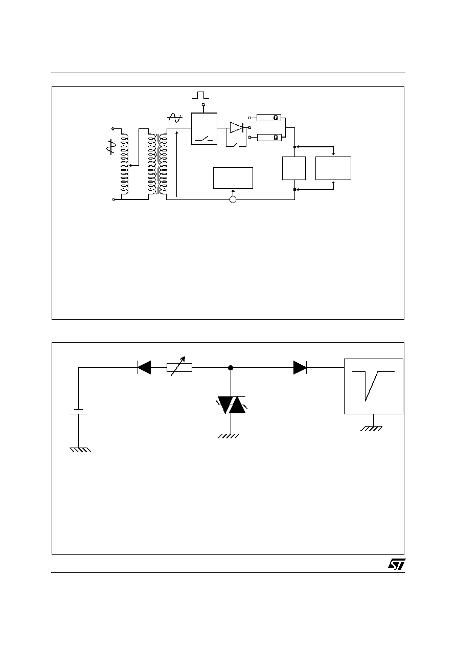
TEST CIRCUIT 2 for I
H
parameter.
R
- V
P
V
BAT
= - 48 V
Surge generator
D.U.T.
This is a GO-NOGO test which allows to confirm the holding current (I
H
) level in a functional
test circuit.
TEST PROCEDURE :
n
1) Adjust the current level at the I
H
value by short circuiting the AK of the D.U.T.
2) Fire the D.U.T with a surge Current : Ipp = 10A , 10/1000
µ
s.
3) The D.U.T will come back off-state within 50 ms max.
THBTxxx11D
5/9
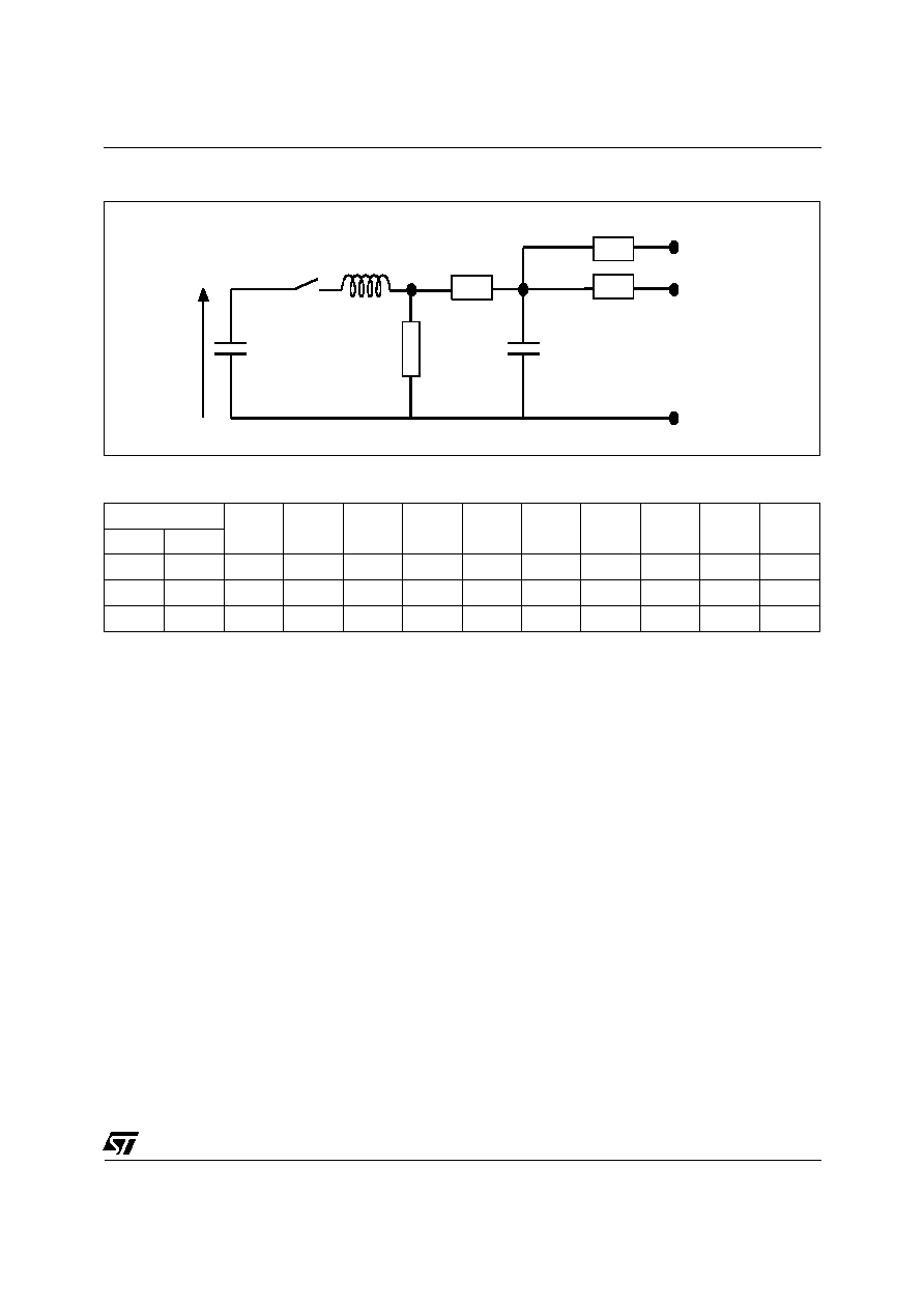
Pulse (
µ
s)
V
p
C
1
C
2
L
R
1
R
2
R
3
R
4
I
PP
R
p
t
r
t
p
(V)
(
µ
F)
(nF)
(
µ
H)
(
)
(
)
(
)
(
)
(A)
(
)
10
700
1500
20
200
0
50
15
25
25
30
10
1.2
50
1500
1
33
0
76
13
25
25
30
10
2
10
2500
10
0
1.1
1.3
0
3
3
38
62
TEST CIRCUIT 3 for I
PP
and V
BO
parameters :
C
C
R
R
TIP
RING
G ND
V
P
4
3
2
R
2
R
1
L
1
(V is defined in no load condition)
P