 | –≠–ª–µ–∫—Ç—Ä–æ–Ω–Ω—ã–π –∫–æ–º–ø–æ–Ω–µ–Ω—Ç: TLP270G-1 | –°–∫–∞—á–∞—Ç—å:  PDF PDF  ZIP ZIP |

TLPxxM/G/G-1
Æ
PowerSO-10
TM
TLPxxM
TRIPOLAR OVERVOLTAGE
PROTECTION for TELECOM LINE
Application Specific Discretes
A.S.D.
TM
September 1998 - Ed : 3C
D
2
PAK TLPxxG
I
2
PAK TLPxxG-1
MAIN APPLICATIONS
Any sensitive telecom equipment requiring protec-
tion against lightning :
Analog and ISDN line cards
Main Distribution Frames
Terminal and transmission equipment
Gas-tube replacement
DESCRIPTION
The TLPxxM/G/G-1 series are tripolar transient
surge arrestors used for primary and secondary
protectionin sensitive telecom equipment.
FEATURES
TRIPOLAR CROWBAR PROTECTION
VOLTAGE
RANGE
SELECTED
FOR
TELECOM APPLICATIONS
REPETITIVE PEAK PULSE CURRENT :
I
PP
= 100 A (10 / 1000
µ
s)
HOLDING CURRENT : I
H
= 150 mA
LOW CAPACITANCE : C = 110 pF typ.
LOW LEAKAGE CURRENT : I
R
= 5
µ
A max
BENEFITS
No ageing and no noise.
If destroyed, the TLPxxM/G/G-1 falls into short
circuit, still ensuring protection.
Access to Surface Mount applications thanks to
the PowerSO-10
TM
and D
2
PAK package.
TM: ASD and PowerSO-10 are trademarks of ST Microelectronics.
RING
TIP
GND
RING
TIP
RING
TIP
RING
TIP
RING
TIP
TAB
GND
GND
RING
TIP
TAB
GND
GND RING
TIP
1/14

COMPLIES WITH THE
FOLLOWING STANDARDS:
Peak Surge
Voltage
(V)
Voltage
Waveform
(
µ
s)
Current
Waveform
(
µ
s)
Admissible
Ipp
(A)
Necessary
Resistor
(
)
CCITT K20
4000
10/700
5/310
100
-
VDE0433
4000
10/700
5/310
100
-
VDE0878
4000
1.2/50
1/20
100
-
IEC-1000-4-5
level 4
level 4
10/700
1.2/50
5/310
8/20
100
100
-
-
FCC Part 68, lightning surge
type A
1500
800
10/160
10/560
10/160
10/560
200
100
-
-
FCC Part 68, lightning surge
type B
1000
5/320
5/320
25
-
BELLCORE TR-NWT-001089
FIRST LEVEL
2500
1000
2/10
10/1000
2/10
10/1000
500
100
-
-
BELLCORE TR-NWT-001089
SECOND LEVEL
5000
2/10
2/10
500
-
CNET I31-24
4000
0.5/700
0.8/310
100
-
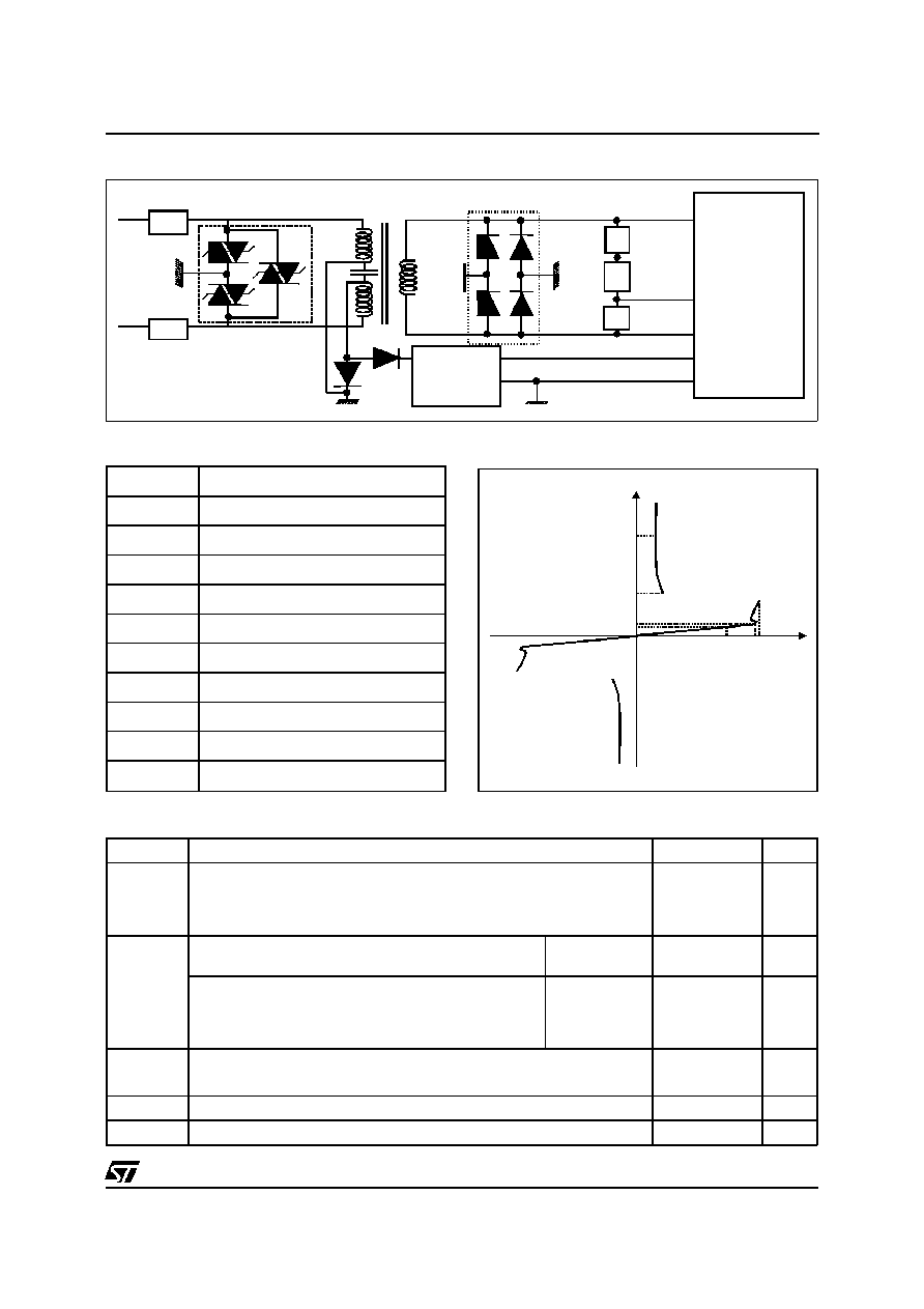
Analog
Main Distribution Frame
Line
Card
TLPxxM/G/G-1
TYPICAL APPLICATION
Primary protection module
TLPxxM/G/G-1
RING
RELAY
LINE A
LINE B
LCP1511D
- V
bat
SLIC
220nF
PTC
PTC
Analog line card protection
TLPxxM/G/G-1
2/14
Symbol
Parameter
Value
Unit
I
PP
Peak pulse current (longitudinal & transversal mode) :
10/1000
µ
s (open circuit voltage waveform 1 kV
10/1000
µ
s)
8/20
µ
s
(open circuit voltage waveform 4 kV
1.2/50
µ
s)
2/10
µ
s
(open circuit voltage waveform 2.5kV
2/10
µ
s)
100
250
500
A
A
A
I
TSM
Mains power induction
VRMS = 300V, R = 600
t = 200ms
0.7
A
Mains power contact
V
RMS
= 220V, R = 10
(Fail-Safe threshold)
t = 200 ms
31
A
V
RMS
= 220V, R = 600
t = 15 mn
0.42
A
T
stg
Storage temperature range
- 55 to + 150
∞
C
Tj
Maximum operating junction temperature
150
∞
C
T
L
Maximum lead temperature for soldering during 10 s
260
∞
C
T
OP
Operating temperature range
- 40 to + 85
∞
C
ABSOLUTE MAXIMUM RATINGS (T
amb
= 25
∞
C)
Symbol
Description
I
PP
Peak pulse current
I
TSM
Maximum peak on-state current
I
R
Leakage current
I
RM
Leakage current
I
H
Holding current
V
BR
Breakdown voltage
V
R
Continuous reverse voltage
V
RM
Maximum stand-off voltage
V
BO
Breakover voltage
C
Capacitance
PARAMETER MEASUREMENT INFORMATION
V
RM
V
R
V
BO
I
H
I
R
I
RM
I
PP
TLPxxM/G/G-1
R4
R5
R3
Feeder
+5
V
1/2 DA108S1
Internal
circuitry
Power
TYPICAL APPLICATION
ISDN: U interface protection
TLPxxM/G/G-1
3/14

Type
I
RM
@ V
RM
I
R
@ V
R
C
max.
max.
typ.
note
µ
A
V
µ
A
V
pF
TLP140M/G/G-1
5
120
50
140
35
TLP200M/G/G-1
5
180
50
200
35
TLP270M/G/G-1
5
230
50
270
35
Note : VR = 50 V bias, VRMS = 1V, F = 1 MHz.
ELECTRICAL CHARACTERISTICS BETWEEN TIP AND RING (T
amb
= 25
∞
C)
Type
I
RM
@ V
RM
I
R
@ V
R
V
BO
@
I
BO
IH
C @ V
R
max.
max.
max.
max.
min.
typ.
note 1
note 2
note 3
note 4
note 5
µ
A
V
µ
A
V
V
mA
mA
pF
pF
TLP140M/G/G-1
5
120
50
140
200
500
150
110
40
TLP200M/G/G-1
5
180
50
200
290
500
150
110
40
TLP270M/G/G-1
5
230
50
270
400
500
150
110
40
Note 1: IR measured at VR guarantees VBR min > VR.
Note 2: Measured at 50 Hz.
Note 3: See functional holding current test circuit.
Note 4: VR = 0V bias, VRMS = 1V, F = 1 MHz.
Note 5: VR = 50V bias, VRMS = 1V, F = 1 MHz (TIP or RING (-) / GND (+)).
ELECTRICAL CHARACTERISTICS BETWEEN TIP AND GND, RING AND GND (T
amb
= 25
∞
C)
Symbol
Parameter
Value
Unit
Rth (j-c)
Junction to case
TLPxxM
TLPxxG
TLPxxG-1
1.0
1.0
1.0
∞
C/W
Rth (j-a)
Junction to ambient
TLPxxM
TLPxxG
TLPxxG-1
see table page 14
see table page 14
see table page 14
∞
C/W
THERMAL RESISTANCE
TLPxxM/G/G-1
4/14
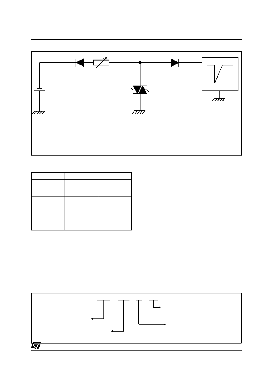
FUNCTIONAL HOLDING CURRENT (I
H
) TEST CIRCUIT: GO-NO GO TEST
R
- V
P
V
BAT
- 48 V
=
Surge generator
D.U.T.
This is a GO-NO GO test which allows to confirm the holding current (I
H
) level in a functional test circuit.
TEST PROCEDURE :
- Adjust the current level at the I
H
value by short circuiting the D.U.T.
- Fire the D.U.T. with a surge current : I
PP
= 10A, 10/1000
µ
s.
- The D.U.T. will come back to the off-state within a duration of 50ms max.
ORDER CODE
Package
Types
Marking
PowerSO-10
TLP140M
TLP200M
TLP270M
TLP140M
TLP200M
TLP270M
D
2
PAK
TLP140G
TLP200G
TLP270G
TLP140G
TLP200G
TLP270G
I
2
PAK
TLP140G-1
TLP200G-1
TLP270G-1
TLP140G
TLP200G
TLP270G
MARKING
TPL
270
M
-
TR
Breakdown Voltage
Packaging:
-TR= tapeandreelonlyfor"M"version(600pcs)
= tube (50 pcs)
Tripolar Line Protection
Package:
M : Power SO10
G : D
2
PAK
G-1 : I
2
PAK
TLPxxM/G/G-1
5/14