 | –≠–ª–µ–∫—Ç—Ä–æ–Ω–Ω—ã–π –∫–æ–º–ø–æ–Ω–µ–Ω—Ç: ZSD301 | –°–∫–∞—á–∞—Ç—å:  PDF PDF  ZIP ZIP |
1/3
January 2002
PSD3XX ZPSD3XX ZPSD3XXV
PSD3XXR ZPSD3XXR ZPSD3XXRV
Low Cost Field Programmable Microcontroller Peripherals
FEATURES SUMMARY
s
Single Supply Voltage:
≠ 5 V±10% for PSD3xx, ZPSD3xx, PSD3xxR,
ZPSD3xxR
≠ 2.7 to 5.5 V for ZPSD3xxV, ZPSD3xxRV
s
Up to 1 Mbit of EPROM
s
Up to 16 Kbit SRAM
s
Input Latches
s
Programmable I/O ports
s
Page Logic
s
Programmable Security
Figure 1. Packages
PLDCC44 (J)
CLDCC44 (L)
PQFP44 (M)
TQFP44 (U)

i
PSD3XX Family
PSD3XX ZPSD3XX ZPSD3XXV
PSD3XXR ZPSD3XXR ZPSD3XXRV
Low Cost Microcontroller Peripherals
Table of Contents
1
Introduction ...........................................................................................................................................................1
2
Notation ................................................................................................................................................................2
3
Key Features ........................................................................................................................................................4
4
PSD3XX Family Feature Summary ......................................................................................................................5
5
Partial Listing of Microcontrollers Supported ........................................................................................................6
6
Applications ..........................................................................................................................................................6
7
ZPSD Background ................................................................................................................................................6
7.1
Integrated Power Management
TM
Operation .............................................................................................7
8
Operating Modes (MCU Configurations) ............................................................................................................10
9
Programmable Address Decoder (PAD).............................................................................................................12
10
I/O Port Functions ...............................................................................................................................................15
10.1
CSIOPORT Registers..............................................................................................................................15
10.2
Port A (PA0-PA7).....................................................................................................................................16
10.2.1 Port A (PA0-PA7) in Multiplexed Address/Data Mode................................................................16
10.2.2 Port A (PA0-PA7) in Non-Multiplexed Address/Data Mode ........................................................17
10.3
Port B (PB0-PB7).....................................................................................................................................18
10.3.1 Port B (PA0-PA7) in Multiplexed Address/Data Mode................................................................18
10.3.2 Port B (PA0-PA7) in Non-Multiplexed Address/Data Mode ........................................................19
10.4
Port C (PC0-PC2) ....................................................................................................................................20
10.5
ALE/AS Input Pin .....................................................................................................................................20
11
PSD Memory ......................................................................................................................................................21
11.1
EPROM....................................................................................................................................................21
11.2
SRAM (Optional)......................................................................................................................................21
11.3
Page Register (Optional) .........................................................................................................................21
11.4
Programming and Erasure.......................................................................................................................21
12
Control Signals ...................................................................................................................................................22
12.1
ALE or AS ................................................................................................................................................22
12.2
WR or R/W...............................................................................................................................................22
12.3
RD/E/DS (DS option not available on 3X1 devices) ................................................................................22
12.4
PSEN or PSEN ........................................................................................................................................22
12.5
A19/CSI ...................................................................................................................................................23
12.6
Reset Input ..............................................................................................................................................24
13
Program/Data Space and the 8031 ....................................................................................................................26
14
Systems Applications..........................................................................................................................................27
15
Security Mode .....................................................................................................................................................30
16
Power Management............................................................................................................................................30
16.1
CSI Input..................................................................................................................................................30
16.2
CMiser Bit ................................................................................................................................................30
16.3
Turbo Bit (ZPSD Only).............................................................................................................................31
16.4
Number of Product Terms in the PAD Logic............................................................................................31
16.5
Composite Frequency of the Input Signals to the PAD Logic..................................................................32
16.6
Loading on I/O Pins .................................................................................................................................33
17
Calculating Power ...............................................................................................................................................34

ii
PSD3XX Family
PSD3XX ZPSD3XX ZPSD3XXV
PSD3XXR ZPSD3XXR ZPSD3XXRV
Low Cost Microcontroller Peripherals
Table of Contents
(cont.)
18
Specifications......................................................................................................................................................37
18.1
Absolute Maximum Ratings .....................................................................................................................37
18.2
Operating Range .....................................................................................................................................37
18.3
Recommended Operating Conditions......................................................................................................37
18.4
Pin Capacitance.......................................................................................................................................37
18.5
AC/DC Characteristics ≠ PSD3XX/ZPSD3XX (All 5 V devices) ..............................................................38
18.6
AC/DC Characteristics ≠ PSD3XXV (3 V devices only)...........................................................................39
18.7
Timing Parameters ≠ PSD3XX/ZPSD3XX (All 5 V devices)....................................................................40
18.8
Timing Parameters ≠ ZPSD3XXV (3 V devices only) ..............................................................................42
18.9
Timing Diagrams for PSD3XX Parts.......................................................................................................44
18.10 AC Testing ...............................................................................................................................................65
19
Pin Assignments .................................................................................................................................................66
20
Package Information ...........................................................................................................................................67
21
Package Drawings ..............................................................................................................................................68
22
PSD3XX Product Ordering Information ..............................................................................................................72
22.1
PSD3XX Selector Guide..........................................................................................................................72
22.2
Part Number Construction .......................................................................................................................73
22.3
Ordering Information................................................................................................................................73
23
Data Sheet Revision History ...............................................................................................................................80

1
1.0
Introduction
Programmable Peripheral
PSD3XX Family
Field-Programmable Microcontroller Peripheral
The low cost PSD3XX family integrates high-performance and user-configurable blocks of
EPROM, programmable logic, and optional SRAM into one part. The PSD3XX products
also provide a powerful microcontroller interface that eliminates the need for external
"glue logic". The part's integration, small form factor, low power consumption, and ease of
use make it the ideal part for interfacing to virtually any microcontroller.
The major functional blocks of the PSD3XX include:
∑
Two programmable logic arrays
∑
256Kb to 1 Mb of EPROM
∑
Optional 16 Kb SRAM
∑
Input latches
∑
Programmable I/O ports
∑
Page logic
∑
Programmable security.
The PSD3XX family architecture (Figure 1) can efficiently interface with, and enhance,
almost any 8- or 16-bit microcontroller system. This solution provides microcontrollers the
following:
∑
Chip-select logic, control logic, and latched address signals that are otherwise
implemented discretely
∑
Port expansion (reconstructs lost microcontroller I/O)
∑
Expanded microcontroller address space (up to 16 times)
∑
An EPROM (with security) and optional SRAM
∑
Compatible with 8031-type architectures that use separate Program and Data Space
∑
Interface to shared external resources.
PSD3XX Family
2
2.
Notation
For a complete product comparison, refer to Table 1.
PSD3XX references the standard version of the PSD3XX family, which are ideal for
general-purpose embedded control applications.
PSD3XXR SRAM-less version of the PSD3XX. If you don't require the 16 Kb SRAM or
need a larger external SRAM, go with this part to save cost.
ZPSD3XX has improved technology that helps reduce current consumption using the Turbo
bit. Excellent if you require a 5 V version of the PSD3XX that uses less power.
ZPSD3XXR SRAM-less version of the ZPSD3XX.
ZPSD3XXV 2.7 V to 5.5 V operation, ideal for very low-power and low-voltage
applications.
ZPSD3XXRV SRAM-less version of the ZPSD3XXV.
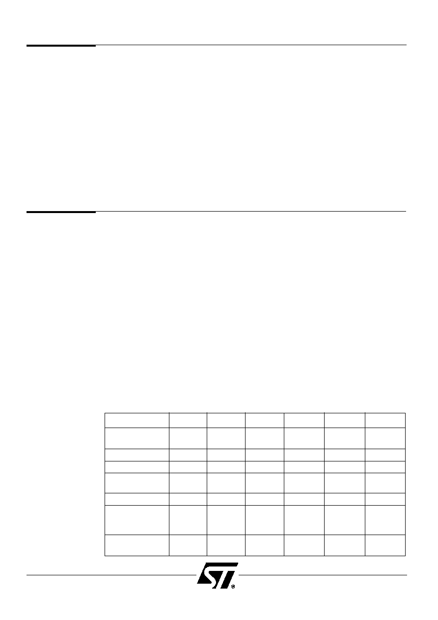
Throughout this data sheet, references are made to the PSD3XX. In most cases, these
references also cover the entire family. Exceptions will be noted. References, such as
"3X1 only" cover all parts that have a 301 or 311 in the part number. Use the following table
to determine what references cover which product versions:
Reference
PSD3XX
PSD3XXR
ZPSD3XX
ZPSD3XXR
ZPSD3XXV
ZPSD3XXRV
PSD3XX
X
X
X
X
X
X
PSD
PSD3XX only
X
X
Non-ZPSD
X
X
ZPSD only
ZPSD3XX
X
X
X
X
Non-V versions
X
X
X
X
V versions only
V suffix
X
X
ZPSD3XXV only
SRAM-less
X
X
X
Non-R
The PSD3XX I/O ports can be used for:
∑
Standard I/O ports
∑
Programmable chip select outputs
∑
Address inputs
∑
Demultiplexed address outputs
∑
A data bus port for non-multiplexed MCU applications
∑
A data bus "repeater" port that shares and arbitrates the local MCU data bus with
external devices.
Implementing your design has never been easier than with PSDsoft --ST's software
development suite. Using PSDsoft, you can do the following:
∑
Configure your PSD3XX to work with virtually any microcontroller
∑
Specify what you want implemented in the programmable logic using a high-level
Hardware Description Language (HDL)
∑
Simulate your design
∑
Download your design to the part using a programmer.
1.0
Introduction
(cont.)