12-13
General Description
(Not recommended for new designs. Please use HV507 with
improved performance.)
The HV35 is a low voltage serial to high voltage parallel converter
with push-pull outputs. This device has been designed for use as
a printer driver for electrostatic applications. It can also be used
in any application requiring multiple output high voltage, low
current sourcing and sinking capabilities.
The device consists of a 64-bit shift register, 64 latches, and
control logic to perform the polarity select and blanking of the
outputs. A DIR pin controls the direction of data shift through the
device. With DIR grounded, D
IOA
is Data-In and D
IOB
is Data-Out;
data is shifted from HV
OUT
64 to HV
OUT
1. When DIR is at logic high,
D
IOB
is Data-In and D
IOA
is Data-Out: data is then shifted from
HV
OUT
1 to HV
OUT
64. Data is shifted through the shift register on
the low to high transition of the clock. Data output buffers are
provided for cascading devices. Operation of the shift register is
not affected by the LE (latch enable), BL (blanking), or the POL
(polarity) inputs. Transfer of data from the shift register to the latch
occurs when the LE (latch enable) is high. The data in the latch is
stored during LE transition from high to low.
A bias pin is used to ensure that the device operates at full V
PP
voltage.
Package Options
Recommended
80-Lead
Device
Operating
Quad Plastic
V
PP
Max
Gullwing
HV3527
275V
HV3527PG
Ordering Information
275V, 64-Channel Serial to Parallel Converter
with High Voltage Push-Pull Outputs
Features
HVCMOS
�
technology
Output voltages up to 275V
Low power level shifting
Shift register speed 6MHz @ V
DD
= 5V
Latched data outputs
Output polarity and blanking
CMOS compatible inputs
Forward and reverse shifting options
Absolute Maximum Ratings
1
Supply voltage, V
DD
-0.5V to +6V
Supply voltage, V
PP
V
DD
to 300V
Logic input levels
-0.5V to V
DD
+0.5V
Ground current
2
1.5A
High voltage supply current
2
1.3A
Continuous total power dissipation
3
1200mW
Operating temperature range
0�C to +70�C
Storage temperature range
-65�C to +150�C
Notes:
1. All voltages are referenced to GND.
2. Connection to all power and ground pads is required. Duty cycle is limited by
the total power dissipated in the package.
3. For operation above 25�C ambient derate linearly to 85�C at 15mW/�C.
HV3527
12-14
HV3527
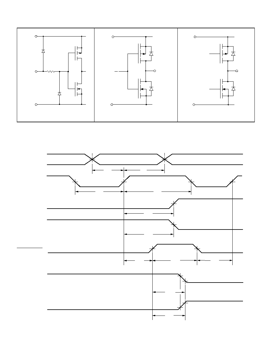
Symbol
Parameter
Min
Typ
Max
Units
Conditions
f
CLK
Clock Frequency
6
MHz
t
W
Clock Width High and Low
High
83
ns
t
SU
Data Setup Time Before Clock Rises
35
ns
t
H
Data Hold Time After Clock Rises
30
ns
t
WLE
Width of Latch Enable Pulse
80
ns
t
DLE
LE Delay Time Rising Edge of Clock
35
ns
t
SLE
LE Setup Time Before Rising Edge of Clock
40
ns
t
ON
, t
OFF
Time from Latch Enable to HV
OUT
1.5
�
s
C
L
= 20pF
t
DHL
Delay Time Clock to Data High to Low
110
ns
C
L
= 20pF
t
DLH
Delay Time Clock to Data Low to High
160
ns
C
L
= 20pF
t
r
, t
f
All Logic Inputs
5
ns
Notes:
1. Shift register speed can be as low as DC as long as Data Set-up and Hold Time meet the spec.
2. AC Characteristics are guaranteed only under V
DD
= 5V.
Symbol
Parameter
Min
Typ
Max
Units
V
DD
Logic supply voltage
4.5
5.0
5.5
V
V
PP
High voltage supply
60
275
V
V
IH
High-level input voltage
V
DD
-0.9
V
DD
V
V
IL
Low-level input voltage
0
0.9
V
T
A
Operating free-air temperature
0
+70
�
C
Notes:
Power-up sequence should be the following:
1. Connect ground.
2. Apply V
DD
.
3. Set all inputs (Data, CLK, Enable, etc.) to a known state.
4. Apply V
PP
.
Power-down sequence should be the reverse of the above.
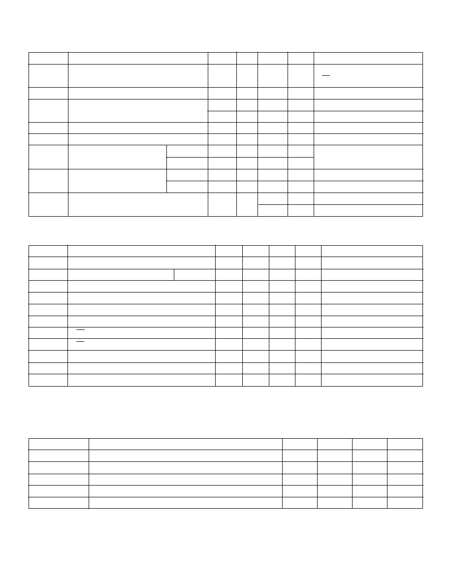
Electrical Characteristics
(over recommended operating conditions unless noted)
Symbol
Parameter
Min
Typ
Max
Units
Conditions
I
DD
V
DD
Supply Current
25
mA
f
CLK
= 6MHz, f
DATA
= 3MHz
LE = LOW
I
DDQ
Quiescent V
DD
Supply Current
200
�
A
All V
IN
= 0V or V
DD
I
PP
High Voltage Supply Current
0.50
mA
V
PP
= 275V All outputs high
0.50
mA
V
PP
= 275V All outputs low
I
IH
High-Level Logic Input Current
10
�
A
V
IH
= V
DD
I
IL
Low-Level Logic Input Current
-10
�
A
V
IL
= 0V
V
OH
High-Level Output
HV
OUT
200
V
V
PP
= 275V, IHV
OUT
= -1mA
Data Out
V
DD
-1V
V
ID
OUT
= -100
�
A
V
OL
Low-Level Output
HV
OUT
10
V
IHV
OUT
= 1mA, V
DD
= 5V
Data Out
1.0
V
ID
OUT
= 100
�
A
V
OC
HV
OUT
Clamp Voltage
V
PP
+1.5
V
I
OL
= +5mA
-1.5
V
I
OL
= -5mA
DC Characteristics
Recommended Operating Conditions
AC Characteristics
1,2
(For V
DD
= 5V; V
PP
= 275V, T
A
= 25
�
C)

12-16
HV3527
HV
OUT
2
�
�
�
60 Additional
Outputs
�
�
�
POL
BL
Latch Enable
Clock
64 bit
Static Shift
Register
64 Latches
HV
OUT
63
V
PP
HV
OUT
1
DIR
D
IOA
V
BIAS
D
IOB
HV
OUT
64
V
PP
V
BIAS
Voltage
V
PP
Operating Voltage
V
BIAS
= 0V or V
PP
V
PP
= 200V
V
BIAS
=
V
PP
= 275V
Functional Block Diagram
V
PP
can be used with a voltage divider
to get V
BIAS
or a separate voltage supply
can be used for V
BIAS
.
R
2
V
PP
V
BIAS
R
1
Inputs
Outputs
Function
Shift Reg
HV Outputs
Data Out
1
2
...
64
1
2
...
64
*
All on
X
X
X
L
L
X
*
*
...
*
H
H
...
H
*
All off
X
X
X
L
H
X
*
*
...
*
L
L
...
L
*
Invert mode
X
X
L
H
L
X
*
*
...
*
*
*
...
*
*
Load S/R
H or L
L
H
H
X
H or L *
...
*
*
*
...
*
*
X
X
H
H
X
*
*
...
*
*
*
...
*
*
X
X
H
L
X
*
*
...
*
*
*
...
*
*
L
H
H
H
X
L
*
...
*
L
*
...
*
*
H
H
H
H
X
H
*
...
*
H
*
...
*
*
D
IOA
X
X
X
L
Q
n
Q
n-1
--
D
IOB
D
IOB
X
X
X
H
Q
n
Q
n+1
--
D
IOA
Notes:
H = high level, L = low level, X = irrelevant,
= low-to-high transition,
= high-to-low transition.
* = dependent on previous stage's state before the last CLK or last LE high.
Data
CLK
LE
BL
POL
DIR
Load/Store Data
in Latches
Transparent
Latch mode
I/O Relation
Function Table
V
BIAS
Table
2
V