
12-29
12
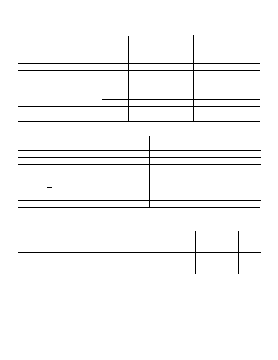
Package Options
80-Lead Quad
Device
Plastic Gullwing
Die
HV4937
HV4937PG
HV4937X
HV4937
64-Channel Serial To Parallel Converter
With P-Channel Open Drain Outputs
Ordering Information
General Description
Not recommended for new designs.
The HV49 is a low voltage serial to high voltage parallel converter
with open drain outputs. It has been designed especially for use
as a driver for electrostatic printers.
This device consists of a 64-bit shift register, 64 latches, a latch
enable (LE), and an output enable (OE). Data is shifted through
the shift register on the high to low transition of the clock. When
the DIR pin is set high, the HV49 shifts in the counterclockwise
direction when viewed from the top of the package. When the DIR
pin is set low, the HV49 shifts in the clockwise direction. A serial
data output buffer is provided for cascading devices. This output
reflects the current status of the last bit of the shift register.
Operation of the shift register is not affected by the LE or the OE
inputs. Transfer of data from the shift register to the latch occurs
when the LE input is high. The data in the latch is stored when LE
is low.
Features
s
HVCMOS
�
Technology
s
Output voltages up to -375V
s
Source current minimum 0.25mA
s
Shift register speed 6 MHz
s
Latched outputs
s
CMOS compatible inputs
s
Forward and reverse shifting options
Absolute Maximum Ratings
1
Supply voltage, V
DD
+0.5V to -9V
Supply voltage, V
PP
+0.5V to -400V
Logic input levels
+0.5V to V
DD
-0.5V
Ground current
0.75A
Continuous total power dissipation
2
1200mW
Operating temperature range
-40
�
C to +85
�
C
Storage temperature range
-65
�
C to +150
�
C
Notes:
1. All voltages are referenced to V
SS
.
2. For operation above 25
�
C ambient derate linearly by 20mW/
�
C up to 85
�
C.
12-30
Symbol
Parameter
Min
Typ
Max
Units
Conditions
f
CLK
Clock Frequency
6
MHz
t
W
Clock Width High or Low
83
ns
t
SU
Data Setup Time Before Clock Falls
35
ns
t
H
Data Hold Time After Clock Falls
15
ns
t
WLE
Width of Latch Enable Pulse
83
ns
t
DLE
LE Delay Time After Falling Edge of Clock
35
ns
t
SLE
LE Setup Time Before Falling Edge of Clock
40
ns
t
DHL
Clock Delay Time Data High to Low
160
ns
t
DLH
Clock Delay Time Data Low to High
160
ns
Electrical Characteristics
(over recommended operating conditions unless noted)
DC Characteristics
Symbol
Parameter
Min
Typ
Max
Units
Conditions
I
DD
V
DD
Supply Current
-15
mA
f
CLK
= 6MHz, f
DATA
= 3MHz
LE = LOW
I
DDQ
Quiescent V
DD
Supply Current
-250
�
A
All V
IN
= 0V
I
O(OFF)
Off State Output Current at 25
�
C, per Switch
-100
nA
Output high, and at -375V
I
IH
High-Level Logic Input Current
-10
�
A
V
IH
= V
DD
I
IL
Low-Level Logic Input Current
+10
�
A
V
I
= 0V
V
OH
High-Level Data Out
V
DD
+1
V
ID
OUT
= -100
�
A
V
OL
Low-Level Output
HV
OUT
-10
V
IHV
OUT
= -0.25mA
Data Out
-1
V
ID
OUT
= 100
�
A
V
OC
HV
OUT
Clamp Voltage
-3.0
V
I
OL
= 1mA
C
HVO
Output Capacitance per Channel
3
pF
V
DS
= 100V
Symbol
Parameter
Min
Typ
Max
Units
V
DD
Logic supply voltage
-4.5
-5.0
-5.5
V
HV
OUT
High voltage output
+0.3
-375
V
V
IH
High-level input voltage
-3.5
V
DD
V
V
IL
Low-level input voltage
0
-0.8
V
T
A
Operating free-air temperature
-40
+85
�
C
Notes:
All voltages are referenced to V
SS.
Power-up sequence should be the following:
1. Connect ground.
2. Apply V
DD
.
3. Set all inputs (Data, CLK, Enable, etc.) to a known state.
4. Apply V
PP
.
Power-down sequence should be the reverse of the above.
Recommended Operating Conditions
AC Characteristics
(For V
DD
= -5V, T
A
= 25
�
C)
HV4937


