 | –≠–ª–µ–∫—Ç—Ä–æ–Ω–Ω—ã–π –∫–æ–º–ø–æ–Ω–µ–Ω—Ç: LLZ6V8 | –°–∫–∞—á–∞—Ç—å:  PDF PDF  ZIP ZIP |
October 2003 / B
Page
1
LLZ
2V
0 through
LLZ
56V
Se
rie
s
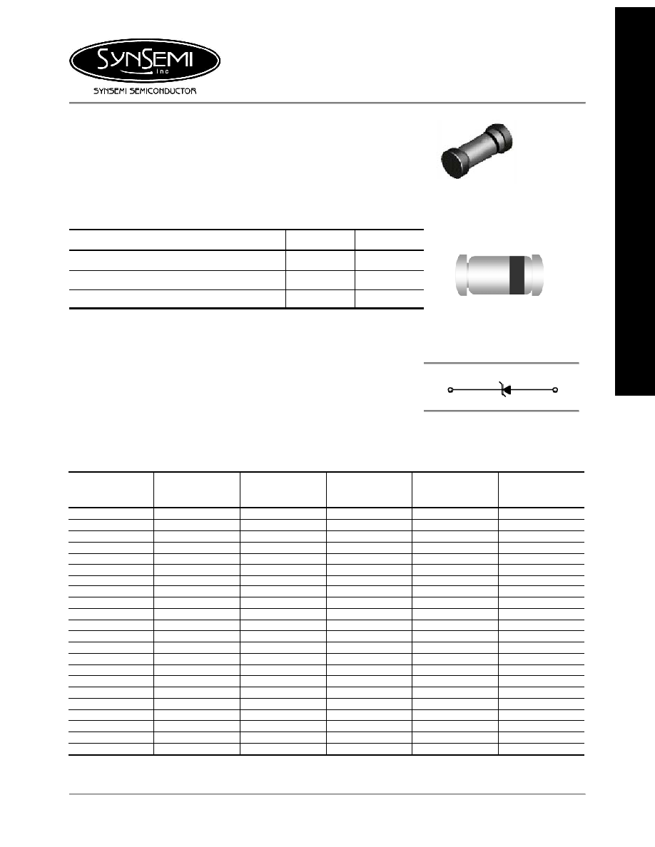
500 mW LL-34 Hermetically
Sealed Glass Zener Voltage
Regulators
Absolute Maximum Ratings
T
A
= 25∞C unless otherwise noted
Parameter Value
Units
Power Dissipation
500
mW
Storage Temperature Range
-65 to +200
∞C
Operating Junction Temperature
+200
∞C
These ratings are limiting values above which the serviceability of the diode may be impaired.
Specification Features:
Zener Voltage Range 2.0 to 56 Volts
LL-34 (Mini-MELF) Package
Surface Device Type Mounting
Hermetically Sealed Glass
Compression Bonded Construction
All external surfaces are corrosion resistant and leads are readily solderable
1
st
band indicates negative polarity
SURFACE MOUNT
LL34 (Mini-MELF)
DEVICE MARKING DIAGRAM
Cathode Band Color : Blue
Anode
Cathode
ELECTRICAL SYMBOL
Electrical Characteristics
T
A
= 25∞C unless otherwise noted
Device Type
V
Z
@ I
ZT
(Volts)
Nominal
I
ZT
(mA)
Z
ZT
@ I
ZT
(
)
Max
I
R
@ V
R
(
µ
A)
Max
V
R
(Volts)
LLZ2V0 2.0
5
100 120 0.5
LLZ2V2 2.2
5
100 120 0.7
LLZ2V4 2.4
5
100 120
1
LLZ2V7 2.7
5
110 100
1
LLZ3V0 3.0
5
120
50
1
LLZ3V3 3.3
5
120
20
1
LLZ3V6 3.6
5
100
10
1
LLZ3V9 3.9
5
100
5
1
LLZ4V3 4.3
5
100
5
1
LLZ4V7 4.7
5
80
5
1
LLZ5V1 5.1
5
80
5
1.5
LLZ5V6 5.6
5
60
5
2.5
LLZ6V2 6.2
5
60
5
3
LLZ6V8 6.8
5
20
2
3.5
LLZ7V5 7.5
5
20
0.5
4
LLZ8V2 8.2
5
20
0.5
5
LLZ9V1 9.1
5
25
0.5
6
LLZ10V 10
5
30 0.2
7
LLZ11V 11
5
30 0.2
8
LLZ12V 12
5
30 0.2
9
LLZ13V 13
5
35 0.2
10
LLZ15V 15
5
40 0.2
11
Electrical Characteristics
T
A
= 25∞C unless otherwise noted
Device Type
V
Z
@ I
ZT
(Volts)
Nominal
I
ZT
(mA)
Z
ZT
@ I
ZT
(
)
Max
I
R
@ V
R
(
µ
A)
Max
V
R
(Volts)
LLZ16V 16
5
40 0.2
12
LLZ18V 18
5
45 0.2
13
LLZ20V 20
5
45 0.2
15
LLZ22V 22
5
30 0.2
17
LLZ24V 24
5
35 0.2
19
LLZ27V 27
5
45 0.2
21
LLZ30V 30
5
55 0.2
23
LLZ33V 33
5
65 0.2
25
LLZ36V 36
5
75 0.2
27
LLZ39V 39
5
85 0.2
30
LLZ43V 43
5
90 0.2
33
LLZ47V 47
5
90 0.2
36
LLZ51V 51
5
110 0.2
39
LLZ56V 56
5
110 0.2
43
V
F
Forward Voltage = 1.2 V Maximum @ I
F
= 200 mA for all types
Notes:
1. The type numbers listed have zener voltage min/max limits as shown and have a standard tolerance on the nominal zener
voltage of 5%.
2. For detailed information on price, availability and delivery of nominal zener voltages between the voltages shown and tighter
voltage tolerances, contact your nearest Synsemi representative.
3. The zener impedance is derived from the 60-cycle ac voltage, which results when an ac current having an rms value equal to
10% of the dc zener current (I
ZT
or I
ZK
) is superimposed to I
ZT
or I
ZK.
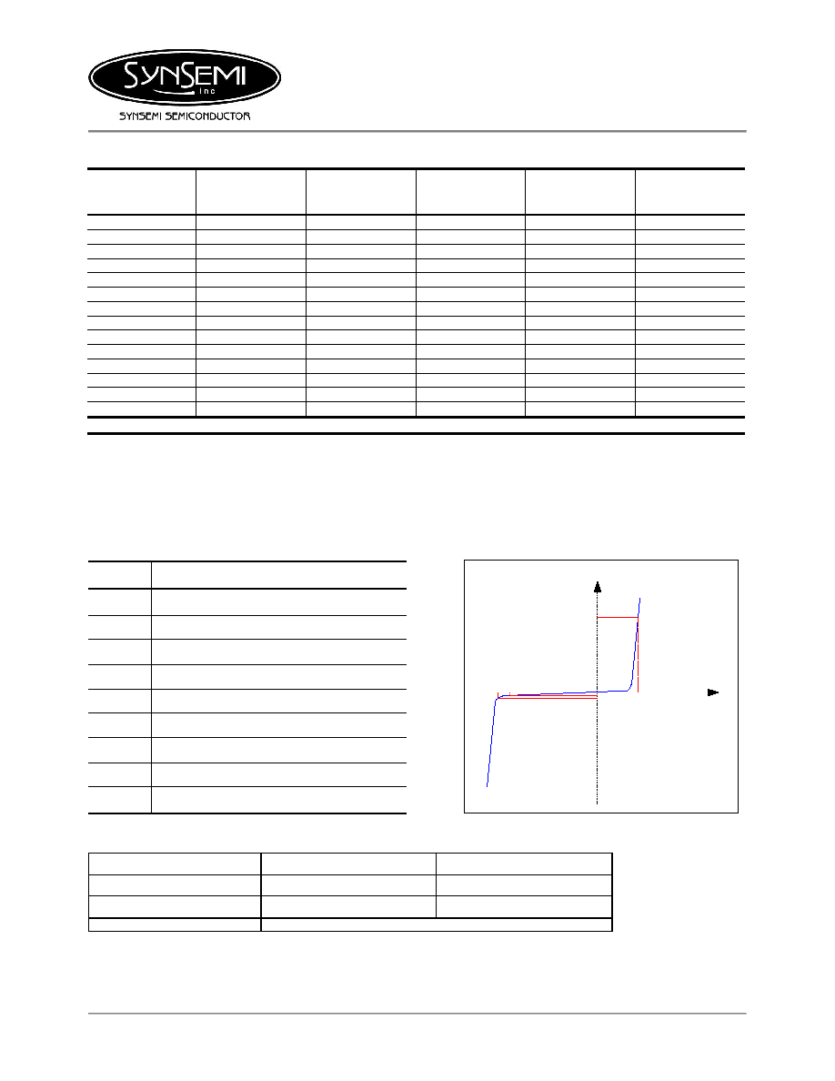
Electrical Symbol Definition
Typical Characteristics
Symbol Parameter
V
Z
Reverse Zener Voltage @ I
ZT
I
ZT
Reverse Current
Z
ZT
Maximum Zener Impedance @ I
ZT
I
ZK
Reverse Current
Z
ZK
Maximum Zener Impedance @ I
ZK
I
R
Reverse Leakage Current @ V
R
V
R
Breakdown Voltage
I
F
Forward Current
V
F
Forward Voltage @ I
F
(nA)
V
Z
V
R
I
R
I
ZT
I
F
V
F
(mA)
(mA)
(V)
(mV)
I
V
Ordering Information
Pack Option
Package
Quantity
7" Reel
Tape and Reel
2500
13" Reel
Tape and Reel
10,000
October 2003 / B
Page
2

LL-34 (Mini-MELF) Tape & Reel Packaging Information
LL-34 Leader and Trailer
LL-34 Packaging Outline
Packaging Description:
LL34 parts are shipped in tape and reel.
The carrier tape is made from a dissipative
(carton filled) polycarbonate resin. The
cover tape is a multiplayer film (Heat
Activated Adhesive in nature) primarily
composed of polyester film, adhesive layer,
sealant, and anti-static sprayed agent.
These reeled parts in standard option are
shipped with 2,500 units per 7" or 178cm
diameter reel. The reels are blue in color
and made of recyclable plastic. Other
option comes in 10,000 units per 13" or
330cm diameter reel
Components
Leader Tape
500mm minimum or
125 empty pockets.
Trailer Tape
80mm minimum or
20 empty pockets.
Cover Tape
Carrier Tape
LL34 UNIT ORIENTATION
Label
Cathode
Static Dissipative Embossed
Carrier Tape
Antistatic Cover Tape
Label
October 2003 / B
Page
3

LL-34 (Mini-MELF) Tape & Reel Packaging Information
LL-34 Reel Outline
Dimensions are in millimeters
Tape Size
QTY Option
Dim A
Dim B
Dim C
Dim D
Dim N
W1
W2
W3
2,500
178
1.5
13
20.2
55
8.4
14.4
7.9 ≠ 10.9
8mm
10,000
330 1.5 13 20.2 100 8.4 14.4
7.9
≠
10.9
October 2003 / B
Page
4

Package Outline
Package Case
Outline
LL34
LL-34
Millimeters Inches
DIM
Min Max Min Max
A
3.302 3.505 0.130 0.138
B
1.397 1.499 0.055 0.059
C
0.350 0.500 0.014 0.020
Notes:
1. LL34 polarity denoted by a band.
2. `Expansion Gap' has no relation to the location of polarity.
October 2003 / B
Page
5