 | –≠–ª–µ–∫—Ç—Ä–æ–Ω–Ω—ã–π –∫–æ–º–ø–æ–Ω–µ–Ω—Ç: 73D2248A | –°–∫–∞—á–∞—Ç—å:  PDF PDF  ZIP ZIP |
73D2248A/2348A
MNP5, V.42bis Datacom
Modem Device Set
April 2000
DESCRIPTION
The 73D2248A/2348A Device Sets consists of two
CMOS integrated circuits which provide the data
pump and protocol functions required to implement a
high performance 2400 bit/s modem with error
control and data compression. The 73D2248A basic
modem function is provided by the 73K224L modem
chip and is compatible with CCITT V.21, V.22,
V.22bis and Bell 103 and 212A protocols. The error
control functions are provided by modular software
running in the 73M2910 controller. Modules are
available for MNP4, and V.42. Compression
software modules can be added to the controller;
MNP5 and V.42bis are available. Provisions for
customization of the command set are provided,
forming the basis for an international modem.
The 73D2348 differs from the 73D2248A in that it
uses the 73K324L instead of the 73K224L for the
data pump. The 73K324L replaces the Bell 103, 300
bps (bit/s) FSK mode of operation, with the CCITT
V.23, 1200 bps (bit/s) FSK mode. The software is
also modified to support V.23. The two products are
otherwise identical.
FEATURES
∑
Combines modem and protocol controller
∑
Supports 0 - 300, 1200 and 2400 bit/s with both
sync and async modes
∑
Modular software design allows customization
∑
Modem protocols:
∑
Bell 103 (73K224L), 212A
∑
CCITT V.21, V.22, V.22bis, V.23 (73K324L)
∑
Error control/compression protocols Available:
MNP4, MNP5, CCITT V.42, V.42bis
∑
Supports non-volatile memory to store user
configurations and phone numbers
∑
CMOS design for low power consumption
MNP5, V.42bis Datacom
Modem Device Set
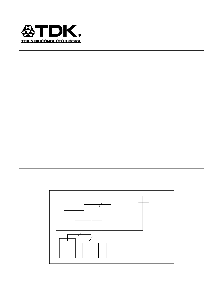
RECOMMENDED
SUPPORT
TSC 73D2248
ROM
64K x 8
STATIC
RAM
32K x 8
73M2910L
Controller
NV
RAM
93C66
HYBRID/
DAA
73K224L/324L
Modem
8
16
16

73D2248A/2348A
MNP5, V.42bis Datacom
Modem Device Set
2
FUNCTIONAL DESCRIPTION
The 73D2248A/2348A device set forms the basis for
an international modem design incorporating the
most advanced error control and compression
algorithms. The set consists of two chips, the
73K224L (73K324L) modem and the 73M2910
controller. Customization of the controller is one of
the features of this device set; software modules
allow the modem vendor to provide a range of
features from a standard hardware platform.
The 73K224L (73K324L) provides the QAM, PSK
and FSK modulator and demodulator functions, call
progress and handshake tone monitors, test modes
and a tone generator capable of producing DTMF,
answer and CCITT guardtones. This single-chip
modem supports the V.22bis, V.22, V.21 and Bell
103/CCITT V.23/212A operating protocols in both
sync and async modes. Low level functions of the
controller provide for automatic detection of DTE
speed, auto-dial, auto-answer, handshake with
fallback and call progress detection.
The 73M2910 controller handles both the low level
modem functions as well as protocol negotiation and
protocol operation. Software modules can be
chosen to provide the desired protocols for product
customization and differentiation. In addition, the
"AT" command set source code will be available for
those desiring to provide unique or country
dependent features.
Basic capabilities of the modem are those found in
the 73K224L (73K324L) single-chip modem and are
listed in the separate 73K224L (73K324L) data
sheet.
AUTOMATIC HANDSHAKE
The 73D2248A/2348A will automatically perform a
complete handshake with a called or calling modem
and enter the data transfer mode. After the link
between the two modems has been established, the
modems may remain in the normal data mode or
negotiate a link which has error control and data
compression. Commands are provided to inform the
modem which action is appropriate.
TEST MODES
The 73D2248A/2348A device set has provisions for
three test modes: analog loopback, digital loopback
and remote digital loopback. Analog loopback
allows data to be sent into the local modem, have it
modulated and then demodulated and returned to
the local terminal. Digital loopback requires the
cooperation of the user at the remote end and allows
data to be sent to the remote modem, demodulated,
then remodulated and returned to the local end.
Remote digital loopback allows the same capability,
without the need for a remote operator; signals are
sent to the remote modem which perform the
switching task that a remote operator would have
done.
AT COMMAND INTERPRETER
The 73D2248A/2348A includes an AT Command
Interpreter which is a superset of the Hayes 2400
Smartmodem
TM
command set. Common application
software will be able to control the modem though
this interpreter. Additional commands have been
added to provide for control of the MNP and CCITT
V.42 modes.
NON-VOLATILE MEMORY
A serial NVRAM provides 256 bytes of storage for
configuration information and telephone numbers.

73D2248A/2348A
MNP5, V.42bis Datacom
Modem Device Set
3
PROTOCOLS
Microcom Networking Protocol (MNP)
MNP4 is a protocol offering error control while MNP5
offers data compression. Data to be transmitted is
broken into blocks of varying sizes, depending on
line conditions, and sent to the remote modem along
with a 16-bit Cyclic Redundancy Check (CRC) word.
If the algorithm used to derive the CRC word at the
transmitter does not produce an identical word when
exercised on the received data, a line error is
assumed, and the block is repeated. Data
compression is obtained by transmitting a short set
of characters for a longer redundant set. At the
receiver, the short string is replaced with the longer
string that it represented, and the data stream is
returned to its original state.
CCITT V.42 AND V.42BIS
The CCITT has ratified a set of protocols which
operate in a manner similar to MNP. MNP4
corresponds to V.42 while MNP5 corresponds with
V.42bis. Greater efficiency is offered, but the
tradeoff is a larger memory space requirement.
MNP5 requires an 8K buffer, while V.42bis requires
32K. Data files which show compression ratios
approaching 2:1 with MNP5 may show ratios of
nearly 4:1 with V.42bis.
ADDITIONAL INFORMATION
The TDK Semiconductor Corporation 73D2248/2348
Design Manual defines the AT commands. Please
contact your local TDK Semiconductor Corporation's
sales office for a copy of the TDK Semiconductor
Corporation's Protocol Design Manual.

73D2248A/2348A
MNP5, V.42bis Datacom
Modem Device Set
4
AT COMMAND SUMMARY
Command
Description
X4
enable features represented by result codes 0-7, 10-12
Y0
disable long space disconnect
Y1
enable long space disconnect
Z0
reset modem
&C0
assume data carrier always present
&C1
track presence of data carrier
&D0
ignore DTR signal
&D1
assume command st ate when an on-to-off
transition of DTR occurs
&D2
hang up and assume command state when an
on-to-off transition of DTR occurs
&D3
reset when an on-to-off transition of DTR occurs
&F
recall factory settings as active configuration
&G0
no guard tone
&G1
550 Hz guard tone
&G2
1800 Hz guard tone
&K
flow control method
&M0
asynchronous mode
&M1
synchronous mode 1
&M2
synchronous mode 2
&M3
synchronous mode 3
&Q5
error control mode
&Q6
automatic speed buffering (ASB)
&T0
terminate test in progress
&T1
initiate local analog loopback
&T3
initiate local digital loopback
&T4
grant request from remote modem for RDL
&T5
deny request from remote modem for RDL
&T6
initiate remote digital loopback
&T7
initiate remote digital loopback with self test
&T8
initiate local analog loopback with self test
&V
view active configuration, user profiles, and stored
numbers
&W0
save storable parameters of active configuration
&X0
modem provides transmit clock signal
&X1
data terminal provides transmit clock signal
&X2
receive carrier provides transmit clock signal
&Zn=x
store phone number "x" in location "n" (0-3)
Command
Description
AT
command prefix - precedes command line
<CR>
carriage return character - terminates command line
A
go into answer mode; attempt to go to on-line state
A/
re-execute previous command line;
not preceded by AT nor followed by <CR>
B0
select CCITT V.22 and V.21standards for 1200 and
300 bit/s communications
B1
select Bell 212A and Bell 103 standards for 1200
and 300 bit/s communicatios
D
dial number that follows; attempt to go to on-line state,
originate mode
DS=n
dial stored number in location "n" (0-3)
E0
Disable character echo in command state
E1
Enable character echo in command state
H0
go on hook (hang up)
H1
go off hook; operate auxiliary relay
I0
request product identification code
I1
perform checksum on firmware ROM; return checksum
I2
perform checksum on firmware ROM;
returns OK or ERROR result codes
L0 or L1
low speaker volume
L2
medium speaker volume
L3
high speaker volume
M0
speaker off
M1
speaker on until carrier detected
M2
speaker always on
M3
speaker on until carrier detected, except during dialing
O0
go to on-line state
O1
go to on-line state and initiate equalizer retrain at
2400 bit/s
Q0
modem returns result codes
Q1
modem does not return result codes
Sr
set pointer to register "r"
Sr=n
set register "r" to value "n"
Sr?
display value stored in register "r"
V0
display result codes in numeric form
V1
display result codes in verbose form (as words)
W0
negotiation progress result codes not returned
W1
negotiation progress result codes returned
X0
enable features represented by result codes 0-4
X1
enable features represented by result codes 0-5, 10-12
X2
enable features represented by result codes 0-6, 10-12
X3
enable features represented by result codes 0-5, 7, 10-12
73D2248A/2348A
MNP5, V.42bis Datacom
Modem Device Set
5
Dial string arguments:
, = delay
@ = silent answer
! = flash
; = return to command
s = dial stored number
W = wait for tone
R = reverse mode
If the NOVRAM has not been initialized it may be necessary to power down/power up and type AT&F&W<cr> to
properly initialize modem state.
TABLE 1: Result Codes
Xn
VERBOSE/NUMERIC RESULT CODES
X0
OK/0, CONNECT/1, RING/2, NO CARRIER/3, ERROR/4
X1
All functions of X0 + CONNECT (RATE)/1 = 300, 5 = 1200, 10 = 2400
X2
All functions of X1 + NO DIAL TONE/6
X3
All functions of X1 + BUSY/7
X4
All functions of X3 + NO DIAL TONE/6, NO ANSWER/8
TABLE 2: S Registers Supported
Sn
FUNCTION
UNITS
DEFAULT
S0
1
Answer on ring
No. of rings on which to answer
000
2
S1
Ring counter
No. of rings accumulated
000
S2
Escape code
ASCII CHR Decimal 0-127
043
S3
Carriage return
ASCII CHR Decimal 0-127
013
S4
Line feed
ASCII CHR Decimal 0-127
010
S5
Back space
ASCII CHR
008
S6
Wait for dial tone
Seconds
002
S7
Wait for carrier
Seconds
030
S8
Pause time
Seconds
002
S9
Carrier valid
100 milliseconds (0.1 sec)
006
S10
Carrier drop out
100 milliseconds (0.1 sec)
014
S11
DTMF tone duration
1 millisecond (0.001 sec)
070
S12
Escape guard time
20 milliseconds (0.05 sec)
050
S13
Unused
N/A
*S14
1
Bit mapped register
Decimal 0-255
170
S15
Unused
N/A
1
Stored in NVRAM with &W command.
2
Modem will not answer until value is changed to 1 or greater.