Specifications which provide more details for the proper and safe use of the described product are available upon request.
All specifications are subject to change without notice.
Inductors
NLC Series NLC3225 Type
For Power Line
SMD
FEATURES
∑ The NLC series feature low DC resistance and high current
handling capacities, making them ideal for power supply line
applications.
∑ They are available in form factors ranging from 2520 to 5650.
APPLICATIONS
Portable telephones, personal computers, hard disk drives, and
other electronic equipment.
SPECIFICATIONS
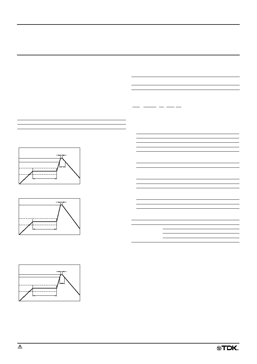
RECOMMENDED SOLDERING CONDITIONS
REFLOW SOLDERING
FLOW SOLDERING
IRON SOLDERING
Perform soldering at 250∞C on 30W max. within 5 seconds.
VAPOR-PHASING
FLUX AND CLEANING
Rosin-based flux is recommended.
Cleaning Conditions
PRODUCT IDENTIFICATION
(1) Series name
(2) Dimensions L
◊
W
◊
T
(3) Packaging style
(4) Inductance value
(5) Inductance tolerance
PACKAGING STYLE AND QUANTITIES
Operating temperature range
≠20 to +85∞C
Storage temperature range
≠40 to +85∞C [Unit of products]
30s max.
Preheating: 120s
10s max.
100∞C
200∞C
230∞C
150∞C
Natural
cooling
Time(s)
Preheating: 120s
10s max.
100∞C
260∞C
150∞C
Natural
cooling
Time(s)
Preheating: 120s
10s max.
100∞C
215∞C
220∞C
150∞C
Natural
cooling
30s max.
Time(s)
Solvent
Chlorine-based solvent
(Do not use acid or alkali solvents.)
Time
2min max.
252018
2.5
◊
2.0
◊
1.8mm
322522
3.2
◊
2.5
◊
2.2mm
453232
4.5
◊
3.2
◊
3.2mm
565050
5.6
◊
5.0
◊
5.0mm
T
Taping(reel)
1R0
1
µ
H
330
33
µ
H
K
±10%
M
±20%
Packaging style
Type
Quantity
Taping
NLC252018T
2000 pieces/reel
NLC322522T
2000 pieces/reel
NLC453232T
500 pieces/reel
NLC565050T
400 pieces/reel
NLC
252018
T-
2R2
M
(1)
(2)
(3)
(4)
(5)
531_NLC3225
980406
Specifications which provide more details for the proper and safe use of the described product are available upon request.
All specifications are subject to change without notice.
Inductors
NLC Series NLC3225 Type
For Power Line
SMD
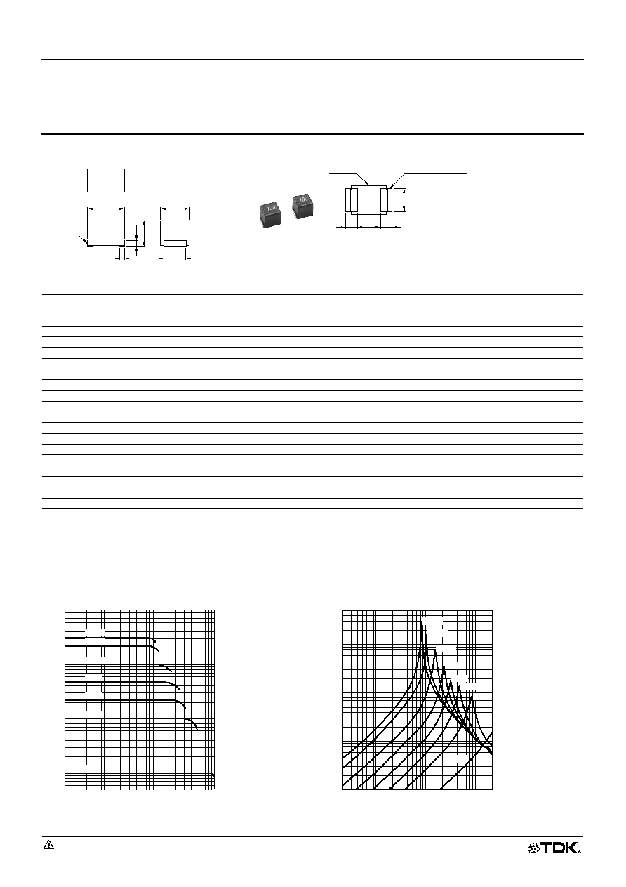
SHAPES AND DIMENSIONS/RECOMMENDED PC BOARD PATTERN
ELECTRICAL CHARACTERISTICS
∑ Test equipment L, Q: YHP4194A IMPEDANCE ANALYZER+YHP16085A+YHP16093B+TF-1, or equivalent
SRF: HP8753C NETWORK ANALYZER (Zin=Zout=50
), or equivalent
Rdc: MATSUSHITA VP-2941A DIGITAL MILLIOHM METER, or equivalent
∑ Marking: Inductance tolerance is omitted to distinguish NL series.
TYPICAL ELECTRICAL CHARACTERISTICS
INDUCTANCE CHANGE vs. DC SUPERPOSITION
CHARACTERISTICS
IMPEDANCE vs. FREQUENCY CHARACTERISTICS
Inductance
(µH)
Inductance
tolerance
Q
min.
Test frequency
L, Q (MHz)
Self-resonant
frequency (MHz)min.
DC resistance
(
)±30%
Rated current
(mA)max.
Part No.
1
±20%
10
7.96
100
0.08
850
NLC322522T-1R0M
1.5
±20%
10
7.96
80
0.11
700
NLC322522T-1R5M
2.2
±20%
10
7.96
68
0.13
600
NLC322522T-2R2M
3.3
±20%
10
7.96
54
0.16
500
NLC322522T-3R3M
4.7
±20%
15
7.96
46
0.2
430
NLC322522T-4R7M
6.8
±20%
15
7.96
38
0.27
360
NLC322522T-6R8M
10
±10%
15
2.52
30
0.36
300
NLC322522T-100K
15
±10%
15
2.52
26
0.56
250
NLC322522T-150K
22
±10%
15
2.52
21
0.77
210
NLC322522T-220K
33
±10%
15
2.52
17
1.1
170
NLC322522T-330K
47
±10%
15
2.52
14
1.64
150
NLC322522T-470K
68
±10%
15
2.52
12
2.8
120
NLC322522T-680K
100
±10%
15
0.796
10
3.7
100
NLC322522T-101K
150
±10%
20
0.796
8
6.1
85
NLC322522T-151K
220
±10%
20
0.796
7
8.4
70
NLC322522T-221K
330
±10%
20
0.796
6
12.3
60
NLC322522T-331K
470
±10%
20
0.796
4
22
45
NLC322522T-471K
680
±10%
20
0.796
3
28
35
NLC322522T-681K
470
3.2
±
0.2
2.5
±
0.2
1.9
±
0.1
Weight: 50mg
2.2
±
0.2
0.5
(0.4)
Terminal
electrode
Solder land pattern
Inductor
2
1
1
2
Dimensions in mm
5
10
50
500
100
1000
5
10
1
50
100
500
1000
Inductance
(
µ
H
)
DC current(mA)
47
µ
H
22
µ
H
330
µ
H
220
µ
H
100
µ
H
10
µ
H
1
µ
H
Frequency(MHz)
1
0.5
10
5
100
50
0.1
1
10
5
0.5
100
50
500
Impedance
( k
)
330
µ
H
220
µ
H
100
µ
H
47
µ
H
22
µ
H
4.7
µ
H
10
µ
H
1
µ
H