Specifications which provide more details for the proper and safe use of the described product are available upon request.
All specifications are subject to change without notice.
531_NLFC4532
(1/2)
Inductors
NLFC Series NLFC4532 Type
For Power Line
SMD
FEATURES
∑ The NLFC series features magnetic shielding and is recom-
mended for power supply line applications.
∑ They are available in 4 form factors ranging from 2016 to 4532.
APPLICATIONS
Personal computers, hard disk drives, and other electronic equip-
ment.
SPECIFICATIONS
RECOMMENDED SOLDERING CONDITIONS
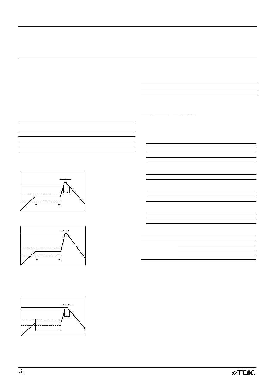
REFLOW SOLDERING
FLOW SOLDERING
IRON SOLDERING
Perform soldering at 250∞C on 30W max. within 5 seconds.
VAPOR-PHASING
FLUX AND CLEANING
Rosin-based flux is recommended.
Cleaning Conditions
PRODUCT IDENTIFICATION
(1)Series name
(2)Dimensions L
◊
W
◊
T
(3)Packaging style
(4)Inductance value
(5)Inductance tolerance
PACKAGING STYLE AND QUANTITIES
Type
Operating temperature
range
Storage temperature
range [Unit of products]
NLFC201614
≠20 to +80∞C
≠40 to +85∞C
NLFC252018
≠20 to +80∞C
≠40 to +85∞C
NLFC322522
≠20 to +80∞C
≠40 to +85∞C
NLFC453232
≠20 to +80∞C
≠40 to +80∞C
30s max.
Preheating: 120s
10s max.
100∞C
200∞C
230∞C
150∞C
Natural
cooling
Time(s)
Preheating: 120s
10s max.
100∞C
260∞C
150∞C
Natural
cooling
Time(s)
Preheating: 120s
10s max.
100∞C
215∞C
220∞C
150∞C
Natural
cooling
30s max.
Time(s)
Solvent
Chlorine-based solvent
(Do not use acid or alkali solvents.)
Time
2min max.
201614
2.1
◊
1.6
◊
1.4mm
252018
2.5
◊
2.0
◊
1.8mm
322522
3.2
◊
2.5
◊
2.2mm
453232
4.5
◊
3.2
◊
3.2mm
T
Taping (reel)
1R0
1
µ
H
220
22
µ
H
K
±10%
M
±20%
Packaging style
Type
Quantity
Taping
NLFC201614T
2000 pieces/reel
NLFC252018T
2000 pieces/reel
NLFC322522T
2000 pieces/reel
NLFC453232T
500 pieces/reel
NLFC
201614
T-
2R2
M
(1)
(2)
(3)
(4)
(5)

531_NLFC4532
010405
Specifications which provide more details for the proper and safe use of the described product are available upon request.
All specifications are subject to change without notice.
531_NLFC4532
(2/2)
Inductors
NLFC Series NLFC4532 Type
For Power Line
SMD
SHAPES AND DIMENSIONS/RECOMMENDED PC BOARD PATTERN
ELECTRICAL CHARACTERISTICS
Rated current: Value obtained when current flows and the temperature has risen to 20∞C or when DC current flows and the initial value of inductance has
fallen by 10%, whichever is smaller.
∑ Test equipment
L, Q: YHP4194A IMPEDANCE ANALYZER+YHP16085A+YHP16093B+TF-1, or equivalent
SRF:HP8753C NETWORK ANALYZER (Zin=Zout=50
), or equivalent
Rdc:MATSUSHITA VP-2941A DIGITAL MILLIOHM METER, or equivalent
TYPICAL ELECTRICAL CHARACTERISTICS
INDUCTANCE CHANGE vs. DC SUPERPOSITION
CHARACTERISTICS
IMPEDANCE vs. FREQUENCY CHARACTERISTICS
Inductance
(µH)
Inductance
tolerance
Q
ref.
Test
frequency
L, Q (MHz)
Self-resonant
frequency
(MHz)min.
DC
resistance
(
)±30%
Rated current (mA)
max.
Part No.
Based on inductance
change
Based on
temperature rise
1
±20%
10
7.96
200
0.05
800
1400
NLFC453232T-1R0M
1.5
±20%
10
7.96
130
0.06
700
1200
NLFC453232T-1R5M
2.2
±20%
10
7.96
80
0.07
600
1100
NLFC453232T-2R2M
3.3
±20%
10
7.96
45
0.09
460
1050
NLFC453232T-3R3M
4.7
±20%
10
7.96
35
0.1
400
1000
NLFC453232T-4R7M
6.8
±20%
10
7.96
28
0.14
300
840
NLFC453232T-6R8M
10
±10%
10
2.52
22
0.21
250
690
NLFC453232T-100K
15
±10%
10
2.52
20
0.3
200
570
NLFC453232T-150K
22
±10%
10
2.52
18
0.46
170
460
NLFC453232T-220K
33
±10%
10
2.52
14
0.63
140
400
NLFC453232T-330K
47
±10%
10
2.52
11.5
0.85
120
340
NLFC453232T-470K
68
±10%
10
2.52
10
1.2
100
280
NLFC453232T-680K
100
±10%
10
0.796
8
1.7
90
240
NLFC453232T-101K
150
±10%
10
0.796
7
2.3
65
200
NLFC453232T-151K
220
±10%
10
0.796
5.5
3.8
55
160
NLFC453232T-221K
330
±10%
10
0.796
4
6
45
120
NLFC453232T-331K
120
C0.5
R0.2
4.5
±
0.3
3.2
±
0.2
3.2
±
0.2
0.5
Terminal
electrode
(0.4)
2.6
±
0.1
Weight: 180mg
Dimensions in mm
2.8
Inductor
Solder land pattern
3
1.5
1.5
1
3
DC current(mA)
10
100
300
30
3000
1000
10000
0.3
0.1
10
100
30
1000
300
Inductance
(
µ
H
)
330
µ
H
100
µ
H
47
µ
H
10
µ
H
4.7
µ
H
1
µ
H
A
L=5H C=20000
µ
F
Test circuit
DC
Universal
bridge
Specimen
YHP model-4275A
or equivalent
1
3
Frequency(MHz)
0.1
1
3
0.3
30
10
100
0.1
0.03
0.01
10
0.3
100
30
Impedance
( k
)
330
µ
H
100
µ
H
47
µ
H
10
µ
H
4.7
µ
H
1
µ
H