∑ All specifications are subject to change without notice.
(1/4)
001-01 / 20030823 / e9632_zj.fm
EMC Components
ZJSR Series
3-Terminal Filters for Signal Line and DC Power Line
Lead(Round)
FEATURES
∑ The ZJSR series combine TDK's high performance ferrite bead
and a chip capacitor. This board mounted EMC filter is used to
prevent microcomputer operational errors and stop noise
generation. Most suitable for use in countering radio noise
generated by digital circuits.
∑ SIP shape with 2.4mm max. thickness, making possible high
density mounting upon a PCB in a row at DIP pitch.
∑ When using taped product, possible to mount using automatic
equipment.
∑ Excellent high frequency bypass performance due to short
earth-side capacitor lead.
PRODUCT IDENTIFICATION
(1)Series name
(2)Capacitance 101:100pF
(3)Packaging style TA: Taping
(not needed for specification of bulk products)
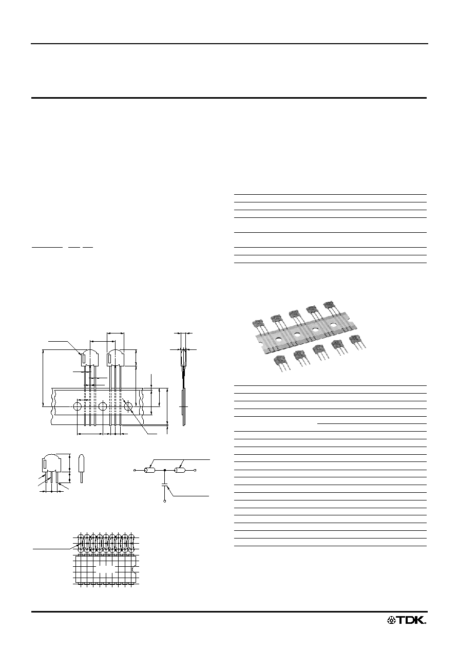
SHAPES AND DIMENSIONS
TAPING SPECIFICATIONS
BULK SPECIFICATIONS
CIRCUIT DIAGRAM
TYPICAL MOUNTING EXAMPLE
APPLICATIONS
Home electronic equipment, (TVs, VCRs, CD players, DAT play-
ers, electric musical instruments, PCs, etc.), office automation
equipment (computers, terminals, stand-alone word processors,
fax machines, etc.), factory automation equipment (robots, numeri-
cal control devices, process controllers, etc.), automotive electron-
ics (automotive engine control units, etc.)
BASIC CHARACTERISTICS
∑ This product should not be used under conditions that exceed those
listed above.
∑ Please note that this product is an EMC filter, so should not be used as a
surge absorber, etc.
Dimensions in mm
∑ The tolerance of lead pitch is the dimensions when a lead is released
from tape. Not available for bulk packaging.
ZJSR5101 - 101 TA
(1)
(2) (3)
A
( W
2
)
W
0
W
1
W
l
1
H
F
1
F
2
¯D
0
P
0
(P
1
)
¯d
2
¯d
2
¯d
1
A
1
H
1
P
Marking
h
h
T
1
3
2
2: Ground terminal
Bead cores
Chip capacitor
3
8max.
l
f
1
f
2
2
1
2.54mm pitch
ZJSR series
IC LSI
Series
ZJSR
Rated voltage Edc
50V
Rated current
5A
Withstand voltage Edc
[Between terminal, No.1, 3 to 2]
125V
Insulation resistance
[DC. 50V for 1 min]
10000M
min.
DC resistance[Terminal No.1 to 3]
0.05
max.
Operating temperature range
≠25 to +85∞C
Series
ZJSR
Component width
A
1
8.5max.
Component height
A
8max.
Component thickness
T
2.4max.
Lead wire diameter
(round)
¯d
1
0.5±0.05
¯d
2
0.6±0.05
Component pitch
P
12.7±1
Feed hole pitch
P
0
12.7±0.3
Feed hole position error
P
1
6.35±0.4
Lead pitch
F
1
, F
2
2.5+0.4, ≠0.1
Component alignment
h
0±2
Tape width
W
18+1, ≠0.5
Cover tape width
W
0
12±0.3
Feed hole position error
W
1
9±0.5
Cover tape position
(W
2
)
(4max.)
Component bottom position
H
20±1
Maximum component height
H
1
28max.
Feed hole diameter
¯D
0
4±0.2
Lead wire protrusion
l
1
0.5max.
Lead wire length
l
5±1.5
Lead pitch
f
1
, f
2
2.5±0.5
∑ All specifications are subject to change without notice.
(2/4)
001-01 / 20030823 / e9632_zj.fm
EMC Components
ZJSR Series
3-Terminal Filters for Signal Line and DC Power Line
Lead(Round)
ELECTRICAL CHARACTERISTICS
* Operating temperature range: +5 to +35∞C
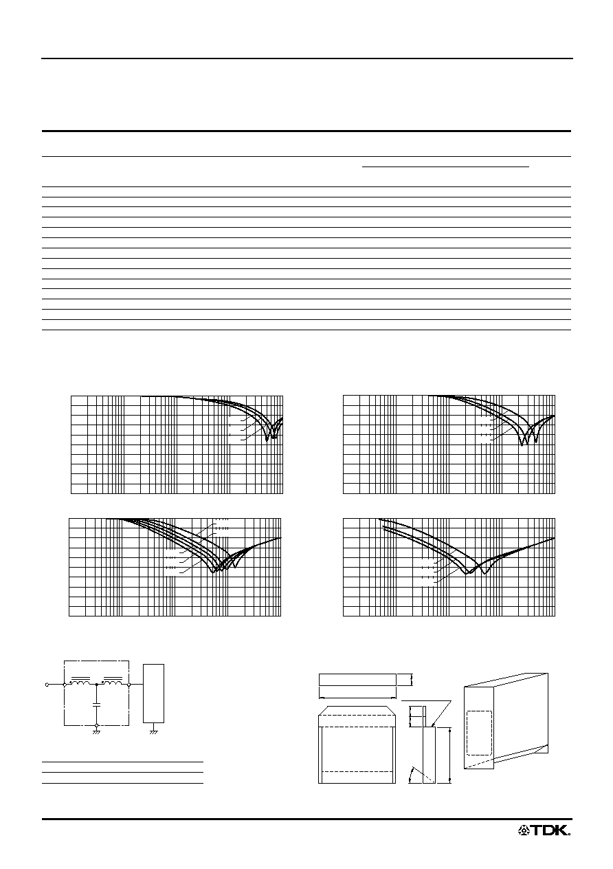
TYPICAL ELECTRICAL CHARACTERISTICS
ATTENUATION vs. FREQUENCY CHARACTERISTICS
Glass epoxy coated double side mounting PCB(t=1.6mm)
CIRCUIT DIAGRAM
PACKAGING STYLE AND QUANTITIES
PACKAGING STYLE
INDICATES INTERIOR
(Ammo-pack)
CONTENTS OF BOX
Part No.
Capacitance
(pF)
Tolerance
(%)
Maximum
attenuation
(MHz)
Frequency range (MHz)[normal mode]*
Marking
15dB min.
attenuation
25dB min.
attenuation
ZJSR5101-330
33
±20
700
400 to 800
650 to 800
330
ZJSR5101-470
47
±20
600
350 to 800
550 to 700
470
ZJSR5101-680
68
±20
500
250 to 800
450 to 600
680
ZJSR5101-101
100
±20
400
200 to 800
350 to 500
101
ZJSR5101-221
220
±20
280
100 to 800
200 to 350
221
ZJSR5101-331
330
±20
220
70 to 800
150 to 300
331
ZJSR5101-102
1000
±20
140
30 to 800
70 to 200
102
ZJSR5101-222
2200
±20
80
20 to 800
45 to 200
222
ZJSR5101-332
3300
±20
70
15 to 800
35 to 200
332
ZJSR5101-472
4700
±20
60
10 to 800
25 to 200
472
ZJSR5101-682
6800
±20
50
8 to 800
20 to 200
682
ZJSR5101-103
10000
+80, ≠20
35
6 to 800
15 to 200
103
ZJSR5101-223
22000
+80, ≠20
27
4 to 800
9 to 200
223
ZJSR5101-333
33000
+80, ≠20
20
3 to 800
7 to 200
333
Attenuation
( dB
)
0.1
100
80
60
40
20
0
1
3
10
30
100
300
1000
0.3
Frequency(MHz)
680
470
330
Attenuation
( dB
)
0.1
100
80
60
40
20
0
1
3
10
30
100
300
1000
0.3
Frequency(MHz)
331
221
101
Attenuation
( dB
)
0.1
100
80
60
40
20
0
1
3
10
30
100
300
1000
0.3
Frequency(MHz)
682
472
332
222
102
Attenuation
( dB
)
0.1
100
80
60
40
20
0
1
3
10
30
100
300
1000
0.3
Frequency(MHz)
333
223
103
Packaging style
Quantity
Taping
2000 pieces/reel
Protective load
2: Ground terminal
1
2
3
42
210
40
25
334
3
5
∞
Sealed opening
EMI/RFI FILTERS
TAPING TYPE
Dimensions in mm
EMI/R
FI FIL
TER
S
TAP
ING
TYP
E
∑ All specifications are subject to change without notice.
(3/4)
001-01 / 20030823 / e9632_zj.fm
EMC Components
ZJSR Series
3-Terminal Filters for Signal Line and DC Power Line
Lead(Round)
TECHNICAL NOTES
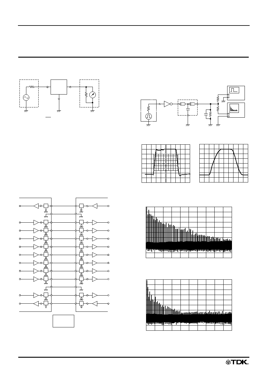
INSERTION ATTENUATION MEASUREMENT METHOD
MOUNTING SUBSTRATE FOR MEASUREMENT
Mount on the glass fabric-backed epoxy resin double-sided
through-hole substrate(t=1.6mm)
MEASUREMENT TEMPERATURE
+5 to +35∞C
TYPICAL APPLICATIONS
An example of radiated noise suppressing circuit by connecting a
PC and a printer.
EXAMPLES OF MEASURING NOISE SUPPRESSION EFFECT
(Waveform spectrum)
(1)MEASUREMENT CIRCUIT
PULSE WAVEFORM
WITHOUT EMC FILTER
WITH EMC FILTER
(2)MEASUREMENT RESULTS
(a)SPECTRUM WITHOUT EMC FILTER
(b)SPECTRUM WITH EMC FILTER
Attenuation = log
10
(dB)
E
2
: Set EMC filter in the circuit
E
1
: Leave EMC filter in the circuit
E
2
E
1
S.G.
L.M.
1
3
2
50
50
EMC
filter
D
0
ACK
D
1
D
2
D
3
D
4
D
5
D
6
D
7
GND
GND
STROBE
BUSY
Computer
Printer
Interface
500
50pF
Pulse generator
EMC filter
Oscilloscope
Spectrum
analyzer
T TL
74AL04S
Output voltage
( 200mV/DIV.
)
Time(10ns/DIV.)
Output voltage
( 200mV/DIV.
)
Time(10ns/DIV.)
0
500
1000
Frequency(MHz)
Amplitude
( dB
µ
V
)
100
80
60
40
20
0
0
500
1000
100
80
60
40
20
0
Frequency(MHz)
Amplitude
( dB
µ
V
)
∑ All specifications are subject to change without notice.
(4/4)
001-01 / 20030823 / e9632_zj.fm
EMC Components
ZJSR Series
3-Terminal Filters for Signal Line and DC Power Line
Lead(Round)
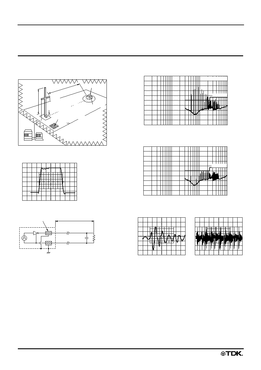
AN EXAMPLE OF MEASURING
NOISE SUPPRESSION EFFECT
(Radiation spectrum)
TTL OUTPUT WAVEFORM WITHIN A SHIELDING CASE
MODEL
RADIATION LEVEL
(a)WITHOUT EMC FILTER
(b)WITH EMC FILTER
BICONICAL ANTENNA INDUCED WAVEFORM
Anechoic chamber
(FCC filed)
Specimen
under test
3m
Antenna
height:
1 to 4m
Vertical/horizontal
polarization planes
Mesh size: less than 30mm
Antenna height above
ground: 25cm
EMC receiver system
Nonconductive
stand
Output voltage
( 200mV/DIV.
)
Time(10ns/DIV.)
900mm
R
C
T TL74ALS04
EMC filter
Shield case
R:500
C:50pF
1000
300
100
30
10
3
1
Frequency(MHz)
Radiation field intensity
( dB
µ
V/m
)
0
20
40
60
80
100
VCCI(3m)
TTL74ALS04
1000
300
100
30
10
3
1
0
20
40
60
80
100
VCCI(3m)
Frequency(MHz)
Radiation field intensity
(dB
µ
V/m)
Induced voltage
( 5mV/DIV.
)
Time(10ns/DIV.)
Induced voltage
( 5mV/DIV.
)
Time(100ns/DIV.)