 | –≠–ª–µ–∫—Ç—Ä–æ–Ω–Ω—ã–π –∫–æ–º–ø–æ–Ω–µ–Ω—Ç: F1250Z8 | –°–∫–∞—á–∞—Ç—å:  PDF PDF  ZIP ZIP |

Four-port TeleLink Fuse
http://www.teccor.com
2 - 48
© 2003 Teccor Electronics
+1 972-580-7777
SIDACtor
Æ
Data Book and Design Guide
Four-port TeleLink Fuse
This hybrid Single In-line Package (SIP) protects four twisted pairs from overcurrent
conditions. Comprising eight TeleLink surface mount fuses, it is ideal for densely populated
line cards that connot afford PCB inefficiencies or the use of series power resistors. F0500T,
F1250T, F1251T versions are available.
* Interrupt test characterized at 50∞ to 70∞ phase angle. Phase angles approximating 90∞ may result in damage to the body of the fuse.
Notes:
∑ The TeleLink SM fuse is designed to carry 100% of its rated current for four hours and 250% of its rated current for one second
minimum and 120 seconds maximum. Typical time is four to 10 seconds. For optimal performance, an operating current of 80% or
less is recommended.
∑ I
2
t is a non-repetitive RMS surge current rating for a period of 16.7 ms.
Notes:
∑ Typical inducta
nce < 150 nH u
p to 500 MHz.
∑ Resistance changes 0.5% for every ∞C.
∑ Resistance is measured at 10% rated current.
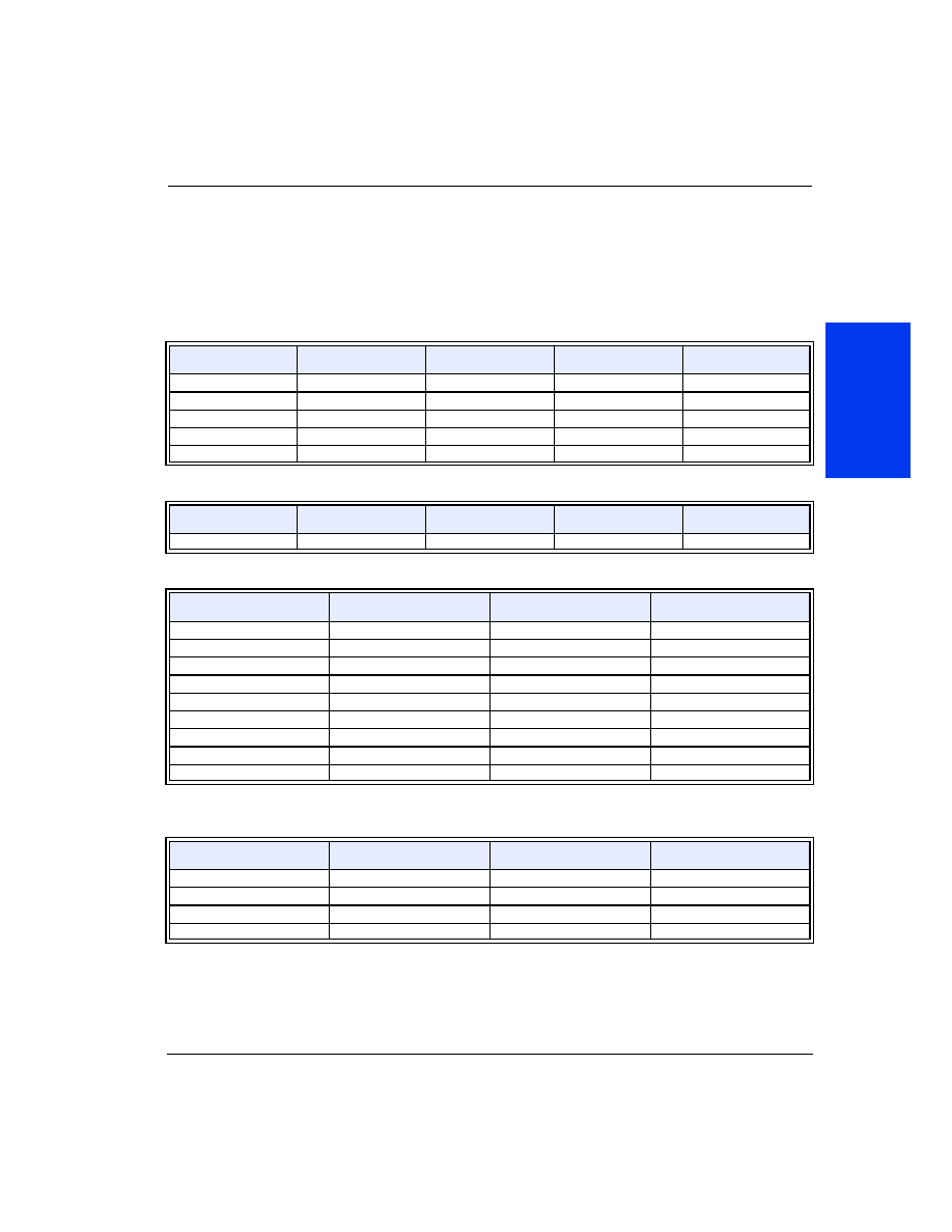
Surge Ratings
TeleLink SM Fuse
I
PP
2x10 µs
Amps
I
PP
10x160 µs
Amps
I
PP
10x560 µs
Amps
I
PP
10x1000 µs
Amps
F0500Z8
not rated
75
45
35
F1250Z8
500
160
115
100
F1251Z8
500
160
115
100
Interrupting Values
TeleLink SM
Fuse
Voltage
Rating
Current
Rating
I
2
t Measured
at DC Rated
Voltage
Interrupting Rating
Voltage, Current
MIN
TYP
MAX
F0500Z8
250 V
500 mA
1.3 A
2
s
600 V, 40 A
1 ms
2 ms
60 ms
F1250Z8
250 V
1.25 A
22.2 A
2
s
600 V, 60 A *
1 ms
2 ms
60 ms
F1251Z8
250 V
2 A
30 A
2
s
600 V, 60 A *
1 ms
2 ms
60 ms
Resistance Ratings
TeleLink SM Fuse
Typical Voltage Drop
@ Rated Current
DC Cold Resistance
MIN
MAX
F0500Z8
0.471 V
0.420
0.640
F1250Z8
0.205 V
0.107
0.150
F1251Z8
0.110 V
0.050
0.100
Four-port TeleLink Fuse
© 2003 Teccor Electronics
2 - 49
http://www.teccor.com
SIDACtor
Æ
Data Book and Design Guide
+1 972-580-7777
D
a
ta
S
h
e
e
ts
Qualification Data
The F1250
Z8
and F1251
Z8
meet the following test conditions per GR 1089 without additional series
resistance. However, in-circuit test verification is required. Note that considerable heating may occur during
Test 4 of the Second Level AC Power Fault Test.
* Test 5 simulates a high impedance induction fault. For specific information, please contact Teccor Electronics.
Notes:
∑ Power fault tests equal or exceed the requirements of UL 60950 3rd edition.
∑ Test 4 is intended to produce a maximum heating effect. Temperature readings can exceed 150 ∞C.
∑ Test 2 may be dependent on the closing angle of the voltage source. Fuse is characterized at 50∞ to 70∞. Closing angles
approximating 90∞ may result in damage to the body of the fuse.
First Level Lightning Surge Test
Test
Surge Voltage
Volts
Wave-form
µs
Surge Current
Amps
Repetitions Each
Polarity
1
±600
10x1000
100
25
2
±1000
10x360
100
25
3
±1000
10x1000
100
25
4
±2500
2x10
500
10
5
±1000
10x360
25
5
Second Level Lightning Surge Test
Test
Surge Voltage
Volts
Wave-form
µs
Surge Current
Amps
Repetitions Each
Polarity
1
±5000
2x10
500
1
First Level AC Power Fault Test
Test
Applied Voltage, 60 Hz
V
RMS
Short Circuit Current
Amps
Duration
1
50
0.33
15 min
2
100
0.17
15 min
3
200, 400, 600
1 at 600 V
60 applications, 1 s each
4
1000
1
60 applications, 1 s each
5
*
*
60 applications, 5 s each
6
600
0.5
30 s each
7
600
2.2
2 s each
8
600
3
1 s each
9
1000
5
0.5 s each
Second Level AC Power Fault Test for Non-Customer Premises Equipment
Test
Applied Voltage, 60 Hz
V
RMS
Short Circuit Current
Amps
Duration
1
120, 277
30
30 min
2
600
60
5 s
3
600
7
5 s
4
100-600
2.2 at 600 V
30 min

Four-port TeleLink Fuse
http://www.teccor.com
2 - 50
© 2003 Teccor Electronics
+1 972-580-7777
SIDACtor
Æ
Data Book and Design Guide
Time Current Curve
Time in seconds
Current in Amperes
.01
.02
.03
.04
.05
.06
.07
.08
.09
.1
.2
.3
.4
.5
.6
.7
.8
.9
1
2
3
4
5
6
7
8
9
10
20
30
40
50
60
70
80
90
100
200
300
400
500
600
700
800
1000
F0500T
F1250T
F1251T
.1
.2
.3
.4
.5
.6 .7 .8 .9 1
2
3
4
5
6
7 8 9 10
20
30
40
50
60 70 80 90100

Four-port TeleLink Fuse
© 2003 Teccor Electronics
2 - 51
http://www.teccor.com
SIDACtor
Æ
Data Book and Design Guide
+1 972-580-7777
D
a
ta
S
h
e
e
ts
Temperature Derating Curve
Operating temperature is -55 ∞C to +125 ∞C with proper correction factor applied.
Chart of Correction Factor
* Higher currents and PCB layout designs can affect this parameter.
Notes:
∑ Readings are measured at rated current after temperature stabilizes
∑ The F1250Z8 meets the requirements of UL 248-14. However, board layout, board trace widths, and ambient
temperature values can cause higher than expected rises in temperature. During UL testing, the typical
recorded heat rise for the F1250Z8 at 2.2 A was 120 ∞C.
∑
Maximum Temperature Rise
TeleLink Fuse
Temperature Reading
F0500Z8
75 ∞C (167 ∞F) *
F1250Z8
75 ∞C (167 ∞F) *
F1251Z8
75 ∞C (167 ∞F) *
30
-55
-60 -40
-20
0
20
40
60
80
100 125
40
50
60
70
80
90
100
110
Ambient ∞C
Percent of Rating
Effect on
Current Rating
120
130
140
150
1
2
3
4
5
Tip
n/c
Ring
F2
F1
6
7
8
9
10
Tip
n/c
Ring
F4
F3
11
12
13
14
15
Tip
n/c
Ring
F6
F5
16
17
18
19
20
Tip
n/c
Ring
F8
F7