”
2002 Teccor Electronics
E8 - 1
http://www.teccor.com
Thyristor Product Catalog
+1 972-580-7777
HT and ST Series
E8
General Description
Teccor's HT and ST Series of bilateral trigger diacs offer a range
of voltage characteristics from 27 V to 45 V.
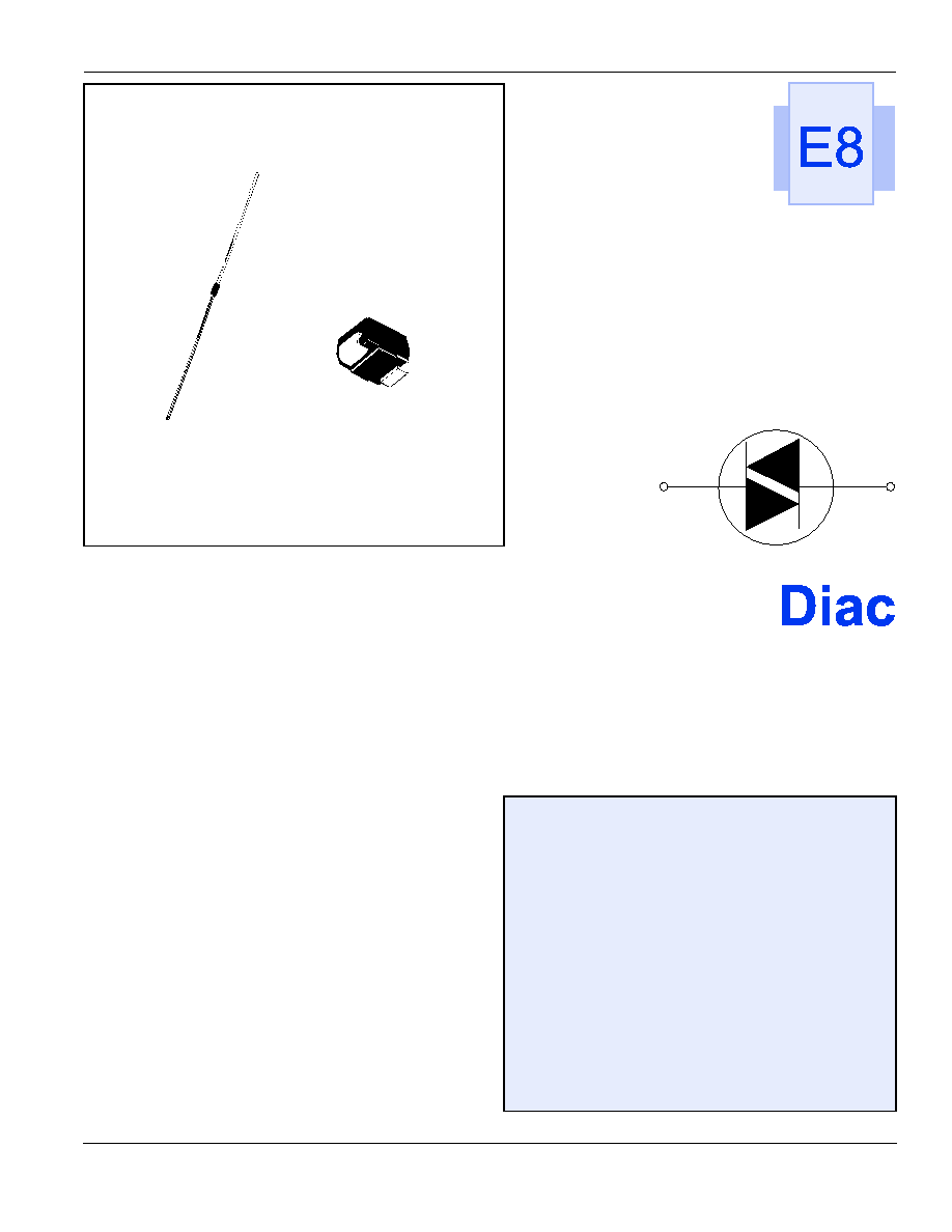
A diac semiconductor is a full-wave or bidirectional thyristor. It is
triggered from a blocking- to conduction-state for either polarity
of applied voltage whenever the amplitude of applied voltage
exceeds the breakover voltage rating of the diac.
The Teccor line of diacs features glass-passivated junctions to
ensure long-term reliability and parameter stability. Teccor's
glass offers a rugged, reliable barrier against junction
contamination.
The diac specifications listed in this data sheet are for standard
products. Special parameter selections such as close tolerance
voltage symmetry are available. Consult the factory for more
information about custom design applications.
Features
∑
Bilateral triggering device
∑
Glass-passivated junctions
∑
Wide voltage range selections
ST Series
∑
Epoxy SMT package
∑
High-temperature, solder-bonded die attachment
HT Series
∑
DO-35 trigger package
∑
Pre-tinned leads
DO-214
DO-35
Diac
Data Sheets
http://www.teccor.com
E8 - 2
”
2002 Teccor Electronics
+1 972-580-7777
Thyristor Product Catalog
General Notes
∑
Lead solder temperature is +230 ∞C for 10-second maximum;
≥1/16" (1.59 mm) from case.
∑
See "Package Dimensions" section of this catalog.
Electrical Specification Notes
(1) Breakover voltage symmetry as close as 1 V is available from the
factory on these products.
(2) See Figure E8.4 and Figure E8.5 for test circuit and waveforms.
(3) Typical switching time is 900 nano-seconds measured at I
PK
(Figure E8.4) across a 20
W resistor (Figure E8.5). Switching time
is defined as rise time of I
PK
between the 10% to 90% points.
(4) See V-I Characteristics.
Bilateral Trigger DIAC Specifications
∑
Maximum Ratings, Absolute-Maximum Values
≠ Maximum Trigger Firing Capacitance: 0.1 µF
≠ Device dissipation (at T
A
= -40 ∞C to +40 ∞C):
250 mW for DO-35 and 300 mW for DO-214
≠ Derate above +40 ∞C:
3.6 mW/∞C for DO-35 and 3 mW/∞C for DO-214
∑
Temperature Ranges
Storage: -40 ∞C to +125 ∞C
Operating (Junction): -40 ∞C to +125 ∞C
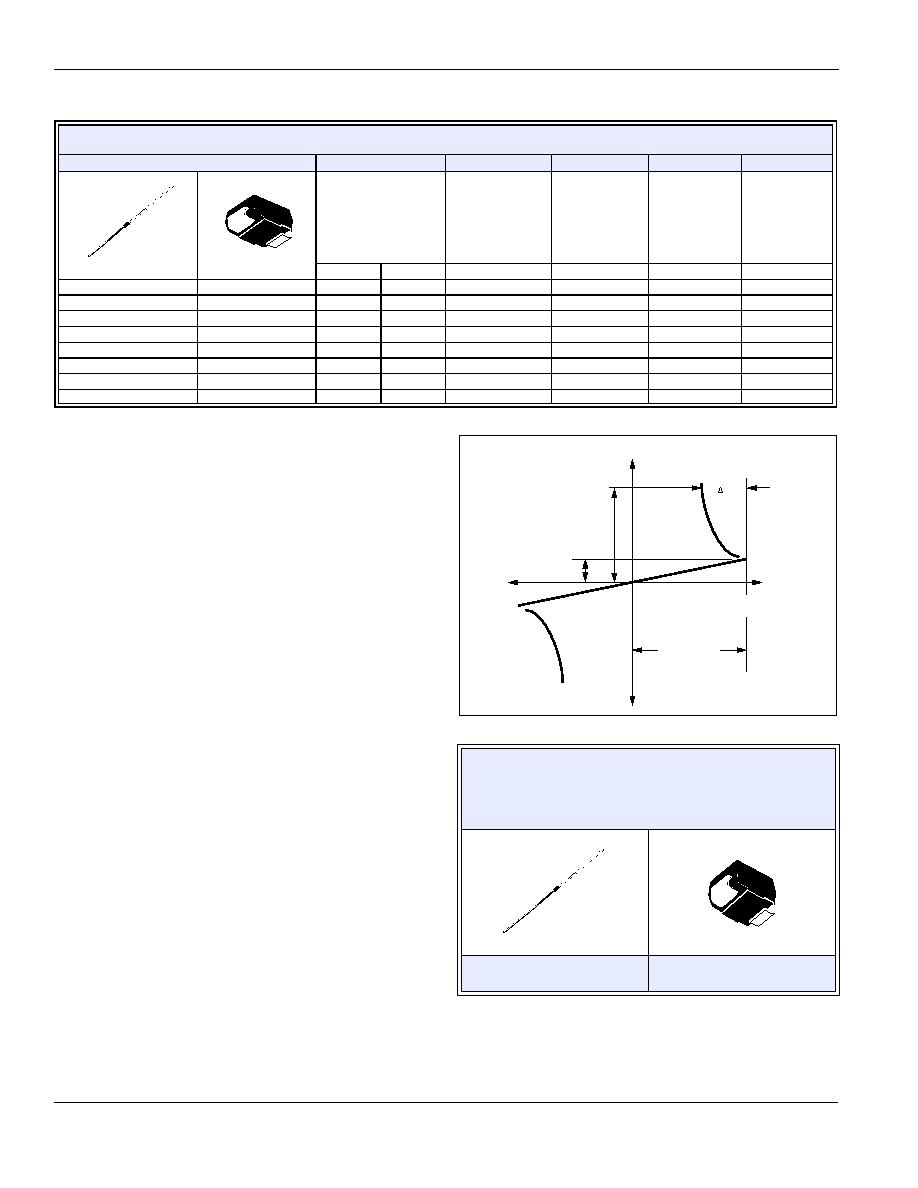
V-I Characteristics
* Mounted on 1 cm
2
copper foil surface; two-ounce copper foil
Electrical Characteristics T
C
= 25∞C
Part No.
V
BO
DV
BO
V
BB
I
BO
I
TRM
DO-35
DO-214
Breakover Voltage
(Forward and
Reverse)
Volts
Breakover Voltage
Symmetry
DV
BO
=
[ | +V
BO
| - | - V
BO
| ]
Volts
Dynamic
Breakback
Voltage
(3)
|
DV± |
Volts
Peak Breakover
Current
at
Breakover
Voltage
µAmps
Peak Pulse
Current
for 10 µs
120 PPS
T
A
£40 ∞C
Amps
MIN
MAX
MAX
MIN
MAX
MAX
HT-32
ST-32
27
37
3 (1)
10 (2)
25
2
HT-32A / HT-5761
28
36
2 (1)
7 at 10 mA (4)
25
2
HT-32B / HT-5761A
ST-32B
30
34
2 (1)
7 at 10 mA (4)
25
2
HT-34B
ST-34B
32
36
2 (1)
10 (2)
25
2
HT-35
ST-35
30
40
3 (1)
10 (2)
25
2
HT-36A / HT-5762
ST-36A
32
40
2 (1)
7 at 10 mA (4)
25
2
HT-36B
ST-36B
34
38
2 (1)
10 (2)
25
2
HT-40
ST-40
35
45
3 (1)
10 (2)
25
2
HT and ST Series Thermal Resistance
Junction to Lead - R
q
JL
: ∞C/W
Junction to Ambient [R
q
JA
]: ∞C/W
(based on maximum lead temperature of
90 ∞C for DO-214 and 85 ∞C for DO-35 devices)
Y Package
DO-35
S Package
DO-214
100 [278] ∞C/W
65 ∞C/W *
10 mA
Breakover
Current
I
BO
-V
BO
Voltage
Current
Breakover
Voltage
V
BO
+V
BO
V

Data Sheets
Diac
”
2002 Teccor Electronics
E8 - 3
http://www.teccor.com
Thyristor Product Catalog
+1 972-580-7777
Figure E8.1 Typical Diac/Triac Full-wave Phase Control Circuit Using
Lower Voltage Diacs.
Figure E8.2 Repetitive Peak On-state Current versus Pulse Duration
120 V ac
60 Hz
LOAD -- Up to 1500 W
3.3 k
200 k
0.1
µF
100 V
HT-35
Bilateral
Trigger
Diac
Triac
Q2015L5
MT2
MT1
G
1
2
4
6
200
400 6001000
2000
4000
10000
.001
.002
.003
.005
0.1
0.2
0.3
3.0
0.5
5.0
.01
0.02
0.03
0.05
1.0
10
2.0
Repetitive Peak On-state Current (I
TRM
) ≠ Amps
Base Pulse Duration ≠ µs
Safe Operating
Area
10
20
40 60 100
PULSE REPETITION RATE = 120 pps
T
A
= 40 ∞C

Diac
Data Sheets
http://www.teccor.com
E8 - 4
”
2002 Teccor Electronics
+1 972-580-7777
Thyristor Product Catalog
Figure E8.3 Normalized V
BO
Change versus Junction Temperature
Figure E8.4 Test Circuit Waveforms (Refer to Figure E8.5.)
Figure E8.5 Circuit Used to Measure Diac Characteristics
(Refer to Figure E8.4.)
Figure E8.6 Peak Output Current versus Triggering Capacitance
(Per Figure E8.5 with R
L
of 20
W)
-8
-6
-4
-2
0
+2
+4
+6
+8
-40
-20
0
+20 +40 +60 +80 +100 +120 +140
Junction Temperature (T
J
) ≠ ∞C
Percentage of V
BO
Change ≠ %
ST Series
HT Series
V+
V-
V
C
0
-V
BO
I
L
+I
PK
0
t
-I
PK
t
+V
BO
Typical pulse base width is 10 µs
120 V rms
60 Hz
47 k
D.U.T.
R
L
20
1%
V
C
100 k
*
C
T
I
L
O.1
µF
*
Adjust for one firing in each half cycle. D.U.T. = Diac
Triggering Capacitance (C
T
) ≠
µF
Peak Output Current (I
PK
) ≠ mA
.01
.02
.03
.04
.05
.06
.07
.08
.09
0
50
100
150
200
250
300
Typical (35 V Device)
.10