 | –≠–ª–µ–∫—Ç—Ä–æ–Ω–Ω—ã–π –∫–æ–º–ø–æ–Ω–µ–Ω—Ç: U2642B-FP | –°–∫–∞—á–∞—Ç—å:  PDF PDF  ZIP ZIP |

U2642B
TELEFUNKEN Semiconductors
Rev. A2, 02-Dec-97
1 (10)
Intermittent- and Wipe/Wash Control for Wiper Systems
Description
With the U264xB, TEMIC Semiconductors developed a
family of intermittent- and wipe/wash control circuits for
windshield or backlite wiper systems with identical basic
functions. The circuit design provides the possibility to
generate "x" versions using different metallization
masks. Thus, it is easy to verify a broad range of time se-
quences which can be set independently of each other.
Features
D Relay activation can be controlled by a limit switch of
the wiper motor or by a fixed activation period for
systems without limit switch
D Debounced input stages
D Enable/disable of pre-wash delay by program pin
D Polarity of WIWA: V
Batt
D Polarity of INT:
V
Batt
D Relay output is protected with a clamping diode
D Relay activation:
0.64 s
D Interval pause:
10 s
D After wiping:
5.8 s
D Pre-wash delay:
0.91 s
D Wipe/wash mode with priority
D Protected in accordance to ISO/TR 7637≠1
D EMC with intergrated filters
Ordering Information
Extended Type Number
Package
Remarks
U2642B
DIP8
U2642B≠FP
SO8
Block Diagram
21 V
21 V
21 V
21 V
Input
comparator
Voltage
stabilization
and
POR
Logic
Load-
dump
detection
and
output
control
Oscillator
21 V
Open-collector
relay driver
V
S
OSC
INT
WIWA
LS
PP
GND
REL
13944
Figure 1.

U2642B
TELEFUNKEN Semiconductors
Rev. A2, 02-Dec-97
2 (10)
Pin Configuration
Pin
Symbol
Function
1
INT
Intermittent input
2
WIWA
Wipe/wash (WIWA) input
3
LS
Limit switch (wiper motor) input
4
PP
Program pin
5
GND
Ground
6
REL
Relay output
7
V
S
Supply voltage
8
OSC
RC oscillator input
OSC
V
S
GND
INT
WIWA
PP
LS
1
2
3
4
8
7
6
5
13365
REL
Figure 2. Pinning
Functional Description
All times specified below refer to an oscillator frequency
of 200 Hz. Figures 2 to 9 show the dependencies of the
times upon battery voltage and temperature. The
temperature dependence of the oscillator frequency is
essentially determined by the temperature coefficient of
the oscillator capacitor. The temperature dependence of
the oscillator frequency can be reduced to minimum with
a slightly negative temperature coefficient (N100). The
capacitor used in figures 10 and 11 has a slightly positive
temperatur coefficient.
All times are permanently set and can be changed only
jointly within certain limits by adjusting the oscillator
frequency. See table 1.
Intermittent Function
The relay is energized for the time t
ON
after the switch
INT is switched on with respect to V
Batt
and after
expiration of time t
D
(debounce).
The debounce time ranges between 60 ms and 80 ms. A
time period of 5 ms to 40 ms for internal sequence control
must be added (asynchronism between operating instant
and internal clock) e.g., the response time may range from
65 ms up to 120 ms.
If the limit switch of the windscreen wiper motor is
connected to Pin LS, the relay is energized as long as the
switch is at high potential, regardless of the relay on-time,
t
ON
, i.e., the motor current in interval mode flows via the
relay contact only. In park position, the motor winding at
both ends is connected to ground via the limit switch and
the motor is decelerated immediately. The limit switch
input is debounced with t
DL
= 17 ms.
The relay on-time, t
ON
, always elapsed ≠ even if the
interval switch was opened beforehand.
Interval Pause
The interval pause t
INT
= 10 s follows t
ON
. Opening of
switch INT causes a debounce time, t
D
, and reclosing
results in the relay on-time, t
ON
, after t
D
.
Wipe/Wash Function without Pre-Wash
Delay (PP connected to GND)
The water pump is switched on when the switch WIWA
is pressed and, after the debounce time, t
D
, the relay is
energized. After-wiping time t
AW
= 5.8 s starts as soon as
switch WIWA is opened and the debounce time, t
D
, has
expired. If the limit switch is connected, the relay remains
energized until the wiper arm returns to park position, i.e.,
the motor current flows via the relay contact only.
Wipe/Wash Function with Pre-Wash Delay
(PP connected to V
S
)
In wipe/wash mode, the relay is energized after a delay
time. The water pump can spray water onto the wind-
screen during the delay time, t
DEL
.
The on-delay time of the U2641B is:
t
DEL
= t
D
+ 0.84 s = 0.91 s
If switch WIWA is closed longer than t
D
but shorter than
t
DEL
, the after-wiping time, t
AW
, starts after expiration of
t
DEL
. The wipe/wash function with or without on-delay
t
DEL
can be selected by programming PP.
PP connected to GND:
without pre-wash delay
PP connected to V
S
:
with pre-wash delay
The after-wiping time, t
AW
, is re-triggerable in both cases.
Intermittent and Wipe/Wash Mode
The wipe/wash function has priority over the interval
function. If switch WIWA is closed during the interval

U2642B
TELEFUNKEN Semiconductors
Rev. A2, 02-Dec-97
3 (10)
function, wipe/wash mode is activated immediately after
the debounce time, t
D
, even if an on-delay is programmed
(t
DEL
= 0 s). Expiry of t
AW
is directly followed by the next
relay on-time, t
ON
, of intermittent mode.
Oscillator
All timing sequences are derived from an RC-oscillator
whose charging time, t
1
, is determined by an external
resistor R
OSC
and whose discharging time, t
2,
is
determinated by an integrated 2-k
W resistor. Since
tolerance and temperature response of the integrated
resistor are far higher than those of the external resistor,
t
1
/t
2
must be selected to be greater than 20 for stability
reasons. The minimum value of R
OSC
should not be less
than 68 k
W.
Calculating cycle duration and frequency:
t = t
1
+ t
2
= C
OSC
( 0.74 R
OSC
+ 2260
W)
and f
OSC
= 1/t
Calculating the capacitor for a given resistor:
C
OSC
= t / ( 0.74
R
OSC
+ 2260
W)
Calculating the oscillator resistance for a given capacitor:
R
OSC
= 1.34
( t / C
OSC
≠ 2260
W)
Recommended frequency: f
OSC
= 200 Hz
(for R
OSC
= 200 k
W, C
OSC
= 33 nF)
All times can be varied jointly within specific limits by
varying the oscillator frequency (see table 1). The oscilla-
tor is operable up to 50 Hz.
Power Supply
For reasons related to protection against interference and
destruction, the Pin V
S
must be provided with an RC net-
work for limiting the current in the event of overvoltage
and for buffering in the event of voltage drops.
Proposed ratings: R
V
= 510
W, C
V
= 47
mF. An integrated
14-V Zener diode is connected between V
S
and GND.
Interference Voltages and Load-Dump
In the case of transients, the integrated Zener diode limits
the voltage of the relay output to approximately 28 V. In
the case of load-dump, a current (dependent upon R
V
and
C
V
) flows through the integrated 14-V Zener diode, and
the relay output is switched on at V
Batt
> 30 V in order to
avoid destruction of the output. The output transistor is
rated such that it can withstand the current generated dur-
ing the load-dump through the relay coil. In practice, the
windscreen wiper motor is switched on via the relay and
thus the amplitude of the load-dump pulse is limited. The
supply voltage of the circuit is limited to 14 V by the inte-
grated Zener diode, and the inputs are protected by
external protective resistors and integrated Zener diodes.
RF suppression is implemented with a low-pass filter at
the inputs, consisting of a protective resistor and the inte-
grated capacitor.
Power-on Reset (POR)
When the supply voltage is applied, a power-on reset
pulse is generated which sets the circuit's logic to a de-
fined initial state. The POR threshold is approximately
V
S
= 4.3 V.
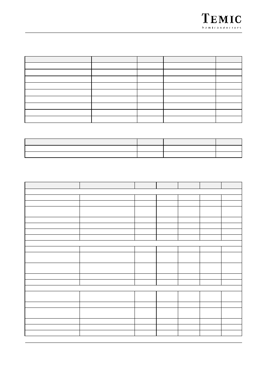
Table 1. Change in times by varying the oscillator frquency
f
osc (Hz)
t
D
[
ms
]
t
DL
[
ms
]
t
ON
[
ms
]
t
INT
[
s
]
t
AW
[
s
]
t
DEL
[
s
]
100
140
35
1280
20.0
11.6
1680
120
116
29
1066
17.0
9.6
1400
140
100
25
915
14.0
8.3
1200
160
87
22
800
12.5
7.2
1050
180
77
19
710
11.0
6.4
933
200
70
17
640
10.0
5.8
840
220
64
16
581
9.0
5.3
763
240
58
14
533
8.2
4.8
700
260
54
13
493
7.6
4.5
645
280
50
12
457
7.0
4.1
600
300
46
11
426
6.5
3.9
560
400
35
9
320
5.0
2.9
420
U2642B
TELEFUNKEN Semiconductors
Rev. A2, 02-Dec-97
4 (10)
Absolute Maximum Ratings
With recommended external circuitry
Parameter
Test Conditions
Symbol
Value
Unit
Supply voltage (static)
5 min
V
Batt
24
V
Supply current pulse
2 ms
I
S
1.5
A
Supply current pulse
300 ms
I
S
150
mA
Relay output current (static)
I
REL
300
mA
Relay output current pulse
300 ms
I
REL
1.5
A
Ambient temperature range
T
amb
≠40 to +95
∞
C
Storage temperature range
T
stg
≠55 to +125
∞
C
Power dissipation
DIP8
P
tot
0.45
W
Power dissipation
SO8
P
tot
0.34
W
Thermal Resistance
Parameters
Symbol
Value
Unit
Junction ambient
DIP8
R
thJA
120
K/W
Junction ambient
SO8
R
thJA
160
K/W
Electrical Characteristics
Reference point Ground GND, T
amb
= 25
_C, V
Batt
= 13.5 V, unless otherwise specified (see figures 11 and 12)
Parameters
Test Conditions / Pin
Symbol
Min
Typ
Max
Unit
Voltage supply
Pin 7
Supply voltage
V
Batt
6.0
16.0
V
Supply current
I
S
0.5
2.0
3.0
mA
Undervoltage threshold
(POR)
V
S
3.0
5.1
V
Internal Z-diode
V
Z
13.5
14.0
16.2
V
Internal capacitor
C
S
15
pF
Series resistance
R
V
510
W
Filter capacitor
C
V
47
mF
Oscillator input OSC
Pin 8
Internal discharge resistor
R
DIS
1.3
2.0
3.2
k
W
Lower switching-point
voltage
V
OSC
0.16
V
S
0.20
V
S
0.24
V
S
V
Upper switching-point
voltage
V
OSC
0.55
V
S
0.60
V
S
0.65
V
S
V
Input current
V
OSC
= 0 V
≠I
OSC
2
mA
Oscillator frequency
f
OSC
1
200
50 k
Hz
Input limit switch LS
Pin 3
Internal protection-diode
voltage
I
LS
= 10 mA
V
LS
19.5
21.0
25.5
V
Internal capacitor
C
LS
25
pF
Switching threshold
voltage
V
LS
0.375
V
S
0.5
V
S
0.675
V
S
V
Input current
V
LS
= V
S
I
LS
1
mA
Internal pull-up resistor
R
LS
13
20
27
k
W
External protection resistor
R
S
10
k
W

U2642B
TELEFUNKEN Semiconductors
Rev. A2, 02-Dec-97
5 (10)
Unit
Max
Typ
Min
Symbol
Test Conditions / Pin
Parameters
Inputs INT, WIWA and PP
Pins 1, 2 and 4
Internal protection-diode
voltage
I
E
= 10 mA
V
E
19.5
21.0
25.5
V
Internal capacitor
C
E
25
pF
Switching threshold
voltage
V
E
0.375
V
S
0.5
V
S
0.675
V
S
V
Input current
V
E
= 0 V
≠I
E
1
mA
Internal pull-down resistor
R
E
13
20
27
k
W
External protection resistor
R
S
10
k
W
Relay Output
Pins 6
Saturation voltage
I = 100 mA
V
REL
1.1
V
Saturation voltage
I = 200 mA
V
REL
1.5
V
Z-diode clamp voltage
I = 10 mA
V
REL
19.5
21.0
25.5
V
Leakage current
V = 14 V
I
REL
12
mA
Relay coil resistance
R
REL
60
W
Load-dump protection
threshold
V
Batt
28
33
42
V
Internal pulse times
Debouncing period inputs
INT/WIWA 12 - 16 clocks
t
D
60
70
80
ms
Debouncing period inputs
LS
3 ≠ 4 clocks
t
DL
15
17.5
20
ms
Relay activation time
96 clocks
t
ON
480
ms
Intermittent pause
t
INT
5.92
s
After wiping period
1024
" 68 clocks
t
WIWA
4.78
5.46
s
Pre-wash delay reaction
time for switch-on delay =
t
DEL
+ t
D
88 ≠ 96 clocks
t
DEL
440
480
ms
Note: All internally generated time sequences are derived from the oscillator frquency. The tolerances refer to a
frequency adjusted to f
OSC
= 200 Hz.