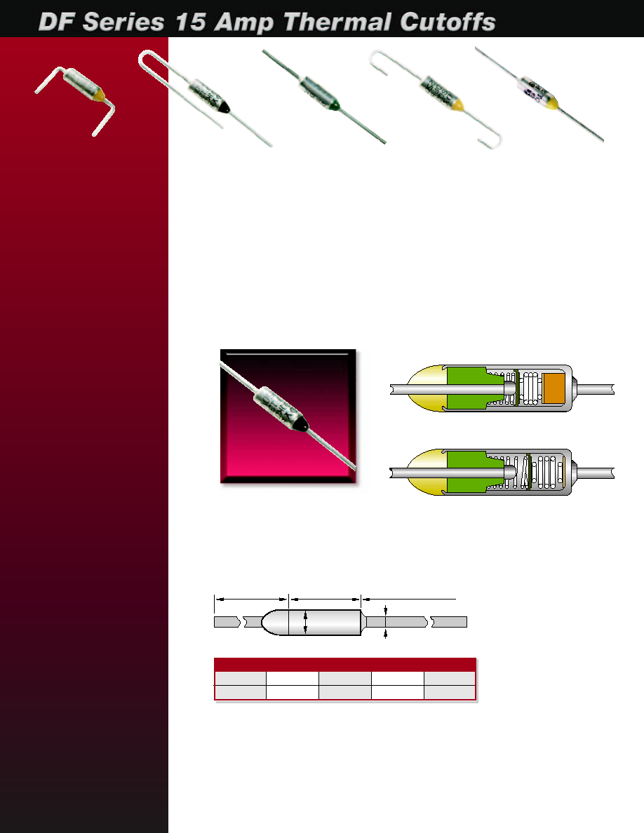
The Thermal DF Series Thermal Cutoffs are single action devices that open when
a preset temperature is reached. They do not reset. The active component of a ther-
mal cutoff is an electrically insulated thermal pellet. This pellet holds a spring loaded
contact against a fixed contact under normal operating temperatures. (See Fig. 1)
When the preset temperature of the cutoff is reached, the pellet liquifies, the springs
relax, and the spring loaded contact is moved away from the fixed contact, opening the
circuit. (See Fig. 2) The DF Series is the right choice for applications requiring an inex-
pensive limit protector with 15A capability.
(Fig. 1) CLOSED
(Fig. 2) OPEN
B
E
C
D
A
FEATURES
∑ Various temperature settings
∑ Miniature size
∑ Current rating: 15 Amp/125
Vac, 10 Amp/250 Vac
∑ Economical
∑ Accurate
∑ Large inventory; same day
shipping
∑ Various mounting options
APPLICATIONS
Thermal cutoffs are widely
used to prevent damage
from overheating in electrical
products
∑ APPLIANCES - space
heaters, irons, stoves,
electric blankets, hair
dryers, clothes dryers,
cookers, toaster ovens,
crock pots, mixers, toasters,
microwave ovens, etc.
∑ MOTORS - air conditioners,
copiers, fans, washing
machines, compressors,
etc.
∑ ELECTRONICS - TVs,
stereos, tape recorders,
video recorders, fluorescent
lamps, transformers,
computers, surge suppres-
sors, telecommunication
equipment, etc.
www.thermtrol.com
E-mail: sales@thermtrol.com
8914 Pleasantwood Ave., N.W. ∑ P.O. Box 2501 ∑ North Canton, OH 44720 ∑ (330) 497-4148 ∑ Fax (330) 497-4189
DF Series
Standard Dimensions (mm)
A
B
C
D
E
25.4±1
10.5±0.5
35±1
¯1±0.05
¯4.0±0.1
Custom lead lengths are available.

Terminology:
Functioning Temperature (TF)
The temperature at which a thermal cutoff changes its state of
conductivity to open a circuit with detection current of 10mA or less
as the only load. The temperature tolerance for the UL and CSA
standard is +0∞C / -10∞C.
Holding Temperature (TH)
The maximum temperature at which a thermal cutoff can be main-
tained while conducting rated current for 168 hrs. without functioning.
Maximum Temperature (TM)
The maximum temperature at which mechanical and electrical prop-
erties of a thermal cutoff can be maintained for 10 minutes without
resuming conductivity after functioning.
Electrical Ratings and Selected Agency Approvals
Functioning
Part
Temperature (∞C)
TH TM 15 Amp/125Vac 15 Amp/125Vac 10 Amp/250Vac
Number
Tol: +0∞C/-4∞C
(∞C) (∞C) 10 Amp/250Vac 10 Amp/250Vac
DF66S
66
42 130
DF72S
72
50 110
DF77S
77
55 130
DF84S
84
60 114
DF91S
91
67 121
DF98S
98
76 130
DF100S
100
78 135
DF104S
104
80 150
DF110S
110
88 140
DF119S
119
95 170
DF128S
128
106 155
DF139S
139
117 170
DF141S
141
117 171
DF144S
144
120 240
DF152S
152
128 175
DF170S
170
146 190
DF184S
184
160 214
DF192S
192
167 210
*
*
DF198S
198
170 244
DF216S
216
186 241
*
*
DF228S
228
193 248
*
*
DF240S
240
200 260
*
*
UL/ CUL: E117626
VDE: 115369, *116219
Precautions When Using
Thermal Cutoffs
The following information describes the correct methods of
using thermal cutoffs to insure proper and safe performance. To
achieve the full use and capacity of a thermal cutoff, it is necessary
for the customer to exercise proper storage and execute appropriate
circuit design, proper installation, and adequate testing. Thermtrol
Corporation does not assume responsibility for problems which occur
as a result of improper storage and installation, or inappropriate
circuit design, evaluations or tests.
∑
Do not use thermal cutoffs for purposes other than for what they are
intended. Thermal cutoffs operate only when they sense an ambient
temperature greater than the factory pre-set temperature. They have
no ability to function by current overload and are not current
limiting devices.
∑
Do not use thermal cutoffs in equipment, appliances or devices
intended to be used in the aerospace industry, aviation, nuclear
power generation systems, life support systems, engine control
systems, or safety control systems for transportation. Thermal cutoffs
are applicable for electrical household devices, appliances and
electronics. Other applications include: office automation equipment,
audiovisual equipment, communication systems, measuring instru-
ments and specific transportation systems.
∑
Do not use thermal cutoffs in applications exceeding the listed
ratings in the specification chart.
∑
Do not use thermal cutoffs in a liquid, in a corrosive atmosphere
such as sulfurous gas, or in a high humidity environment.
∑
Customers shall choose the thermal cutoff appropriate for the
application and determine the proper mounting position and/or
method. To judge whether the selected thermal cutoff and chosen
position and method of mounting is suitable for the final application,
we recommend that the customer fully test and evaluate the unit in an
environment that duplicates the final application as closely as
possible. This includes mounting and securing the thermal cutoff
identically to the method that will be used in production.
Opening Temp.
Max. Soldering Time
Under 120∞ C
2 seconds
Over 120∞ C
3 seconds
Maximum soldering time at solder bath
temperature of 300∞C
Handling and Installation
Instructions
When using thermal cutoffs, considerable caution should be exer-
cised as follows:
A. Installation
∑
Mount the thermal cutoff in a location where uniform radiation of
heat is sustained over the body of the unit.
∑
Keep the leads as long as possible to maximize the area of expo-
sure to heat.
∑
Place and connect the thermal cutoff in a manner so that no
external mechanical force will be applied to the body and/or leads of
the thermal cutoff.
∑
Allow adequate space for mounting the thermal cutoff.
B. Lead Bending
∑
When bending a lead, bend at a location 5mm minimum from the
body of the thermal cutoff.
∑
Take caution not to damage either the thermal cutoff body or the lead.
∑
Keep the thermal cutoff body free from any push, pull or twist force.
C. Soldering
NOTE: The special sealant joining the lead wires to the case will
soften during soldering. Care must be taken to not move the leads
or body during the soldering process as the softened joints could
shift and become disconnected. The sealant will resume its initial
strength after cooling.
∑
Minimize the conduction of excessive heat to the thermal cutoff
body when soldering.
∑
Maximum soldering time is shown in table above.
∑
Solder 20 mm minimum from the thermal cutoff body.
∑
During soldering, both the thermal cutoff body and leads should be
free of any push, pull or twist force.
∑
After soldering, allow the thermal cutoff to cool for 30
seconds minimum without moving it.
12/13
c
Approved
Pending