 | –≠–ª–µ–∫—Ç—Ä–æ–Ω–Ω—ã–π –∫–æ–º–ø–æ–Ω–µ–Ω—Ç: BQ2002 | –°–∫–∞—á–∞—Ç—å:  PDF PDF  ZIP ZIP |
1
Features
Fast charge of nickel cadmium
or nickel-metal hydride batter-
ies
Direct LED output displays
charge status
Fast-charge termination by -
V,
maximum voltage, maximum
temperature, and maximum
time
Internal band-gap voltage ref-
erence
Optional top-off charge
Selectable pulse trickle charge
rates
Low-power mode
8-pin 300-mil DIP or 150-mil
SOIC
General Description
The bq2002 and bq2002/F Fast-Charge
ICs are low-cost CMOS battery-charge
controllers providing reliable charge
termination for both NiCd and NiMH
battery applications.
Controlling a
current-limited or constant-current
supply allows the bq2002/F to be the
basis for a cost-effective stand-alone or
system-integrated charger.
The
bq2002/F integrates fast charge with
optional top-off and pulsed-trickle con-
trol in a single IC for charging one or
more NiCd or NiMH battery cells.
Fast charge is initiated on application
of the charging supply or battery re-
placement. For safety, fast charge is
inhibited if the battery temperature
and voltage are outside configured
limits.
Fast charge is terminated by any of
the following:
n
Peak voltage detection (PVD)
n
Negative delta voltage (-
V)
n
Maximum voltage
n
Maximum temperature
n
Maximum time
After fast charge, the bq2002/F op-
tionally tops-off and pulse-trickles the
battery per the pre-configured limits.
Fast charge may be inhibited using
the INH pin. The bq2002/F may also
be placed in low-standby-power mode
to reduce system power consumption.
T h e b q 2 0 0 2 F d i f f e r s f r o m t h e
bq2002 only in that a slightly differ-
ent set of fast-charge and top-off
time limits is available. All differ-
ences between the two ICs are illus-
trated in Table 1.
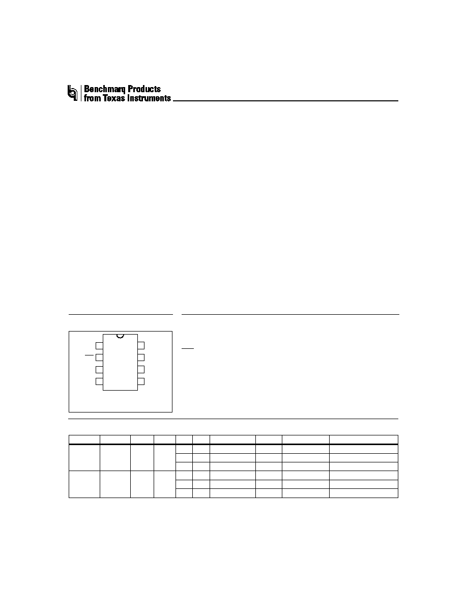
NiCd/NiMH Fast-Charge Management ICs
bq2002/F
TM
Timer mode select input
LED
Charging status output
BAT
Battery voltage input
V
SS
System ground
1
PN-200201.eps
8-Pin DIP or
Narrow SOIC
2
3
4
8
7
6
5
TM
LED
BAT
VSS
CC
INH
VCC
TS
TS
Temperature sense input
V
CC
Supply voltage input
INH
Charge inhibit input
CC
Charge control output
Pin Connections
Pin Names
bq2002/F Selection Guide
Part No.
TCO
HTF
LTF
-
V PVD Fast Charge
t
MTO
Top-Off
Maintenance
bq2002
0.5
V
CC
None
None
C/2
160
C/32
C/64
1C
80
C/16
C/64
2C
40
None
C/32
bq2002F 0.5
V
CC
None
None
C/2
160
C/32
C/64
1C
100
C/16
C/64
2C
55
None
C/32
SLUS131≠JANUARY 1999 D
Pin Descriptions
TM
Timer mode input
A three-level input that controls the settings
for the fast charge safety timer, voltage ter-
mination mode, top-off, pulse-trickle, and
voltage hold-off time.
LED
Charging output status
Open-drain output that indicates the charging
status.
BAT
Battery input voltage
The battery voltage sense input. The input to
this pin is created by a high-impedance re-
sistor divider network connected between
the positive and negative terminals of the
battery.
V
SS
System ground
TS
Temperature sense input
Input for an external battery temperature
monitoring thermistor.
V
CC
Supply voltage input
5.0V
±20% power input.
INH
Charge inhibit input
When high, INH suspends the fast charge in
progress.
When returned low, the IC re-
sumes operation at the point where initially
suspended.
CC
Charge control output
An open-drain output used to control the
charging current to the battery. CC switch-
ing to high impedance (Z) enables charging
current to flow, and low to inhibit charging
current. CC is modulated to provide top-off,
if enabled, and pulse trickle.
Functional Description
Figure 2 shows a state diagram and Figure 3 shows a
block diagram of the bq2002/F.
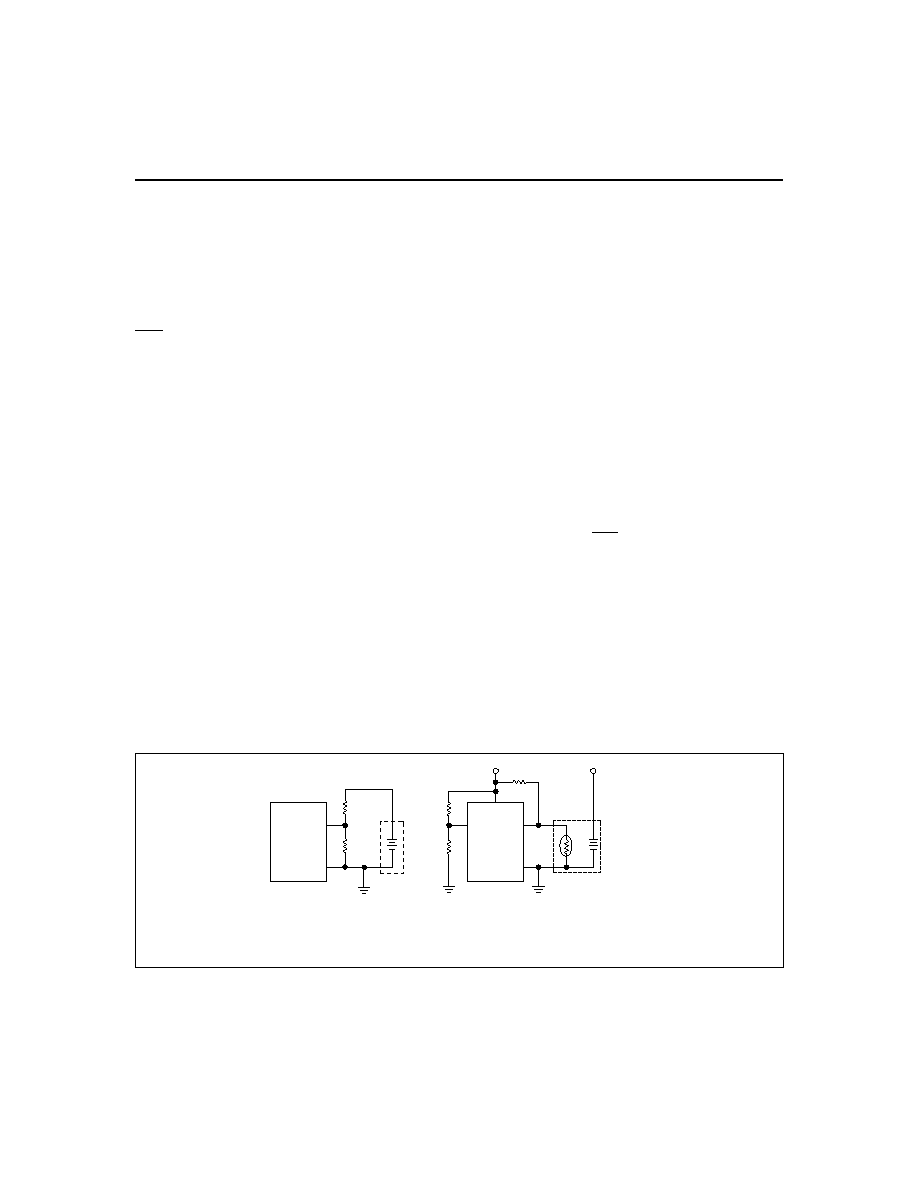
Battery Voltage and Temperature
Measurements
Battery voltage and temperature are monitored for
maximum allowable values. The voltage presented on
the battery sense input, BAT, should represent a
single-cell potential for the battery under charge.
A
resistor-divider ratio of
RB1
RB2
= N - 1
is recommended to maintain the battery voltage within
the valid range, where N is the number of cells, RB1 is
the resistor connected to the positive battery terminal,
and RB2 is the resistor connected to the negative bat-
tery terminal. See Figure 1.
Note: This resistor-divider network input impedance to
end-to-end should be at least 200k
and less than 1 M.
A ground-referenced negative temperature coefficient
thermistor placed near the battery may be used as a low-
cost temperature-to-voltage transducer. The temperature
sense voltage input at TS is developed using a resistor-
thermistor network between V
CC
and V
SS
. See Figure 1.
2
bq2002/F
Fg2002/F01.eps
bq2002/F
BAT
VSS
N
T
C
bq2002/F
VCC
VCC
PACK +
TS
VSS
BAT pin connection
Thermistor connection
TM
NTC = negative temperature coefficient thermistor.
RT
R3
R4
RB1
RB2
Mid-level
setting for TM
Figure 1. Voltage and Temperature Monitoring and TM Pin Configuration
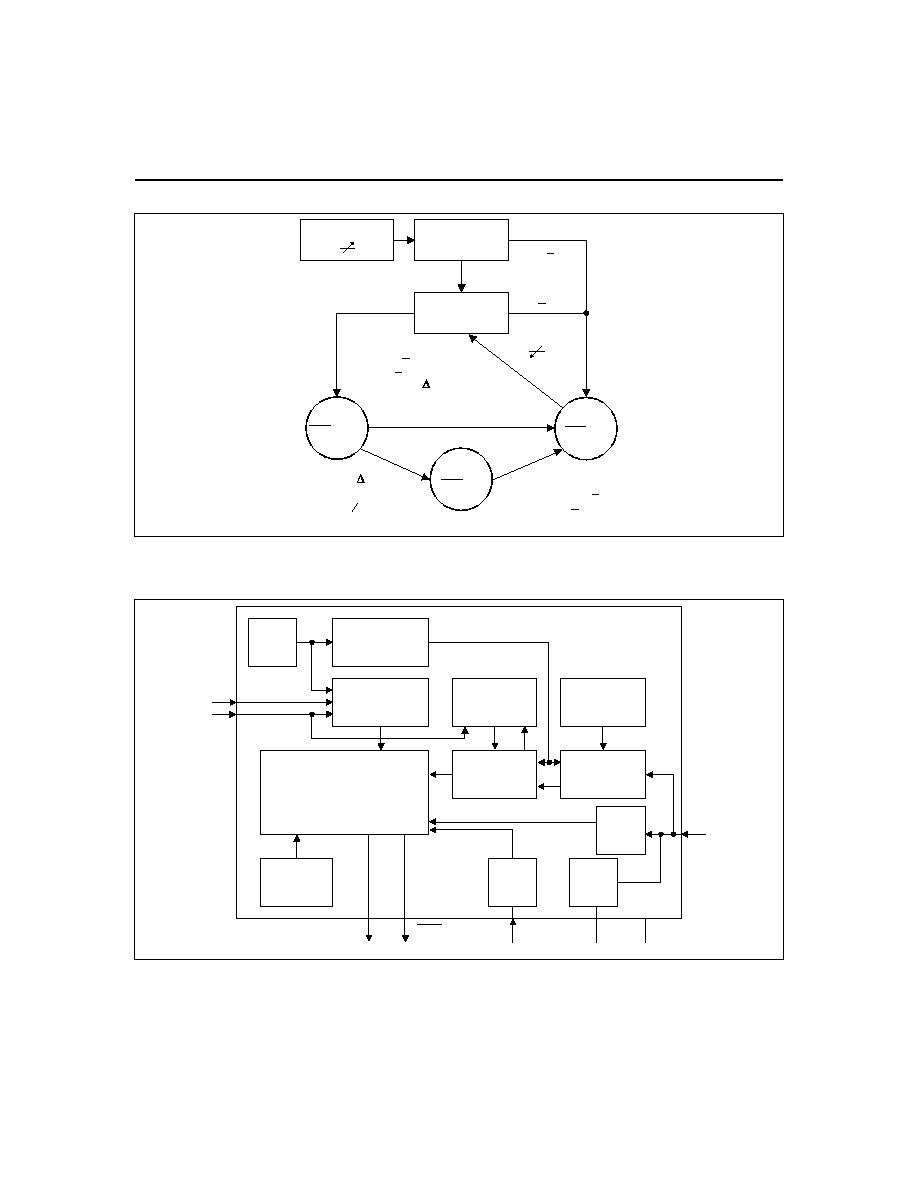
3
bq2002/F
Battery
Temperature?
Battery
Voltage?
Chip on
VCC 4.0V
VCC 2V
Top-off
LED = Z
Trickle
LED = Z
Fast
LED = Low
Maximum Time-Out
or
or
VBAT < 2V
VBAT > 2V
SD2002/F01
VTS > VCC/2
VTS < VCC/2
VBAT > 2V
VBAT > 2V
VTS < VCC/2
VTS < VCC/2
((PVD or - V or
Maximum Time-Out)
and TM = high)
(PVD or - V or
Maximum Time-Out)
and TM = high
Figure 2. State Diagram
OSC
TM
CC
LED
VCC
VSS
BAT
INH
Clock
Phase
Generator
Timing
Control
Sample
History
A to D
Converter
MCV
Check
TS
Bd2002f.eps
Voltage
Reference
PVD, -
V
ALU
Power-On
Reset
TCO
Check
Power
Down
Charge-Control
State Machine
Figure 3. Block Diagram
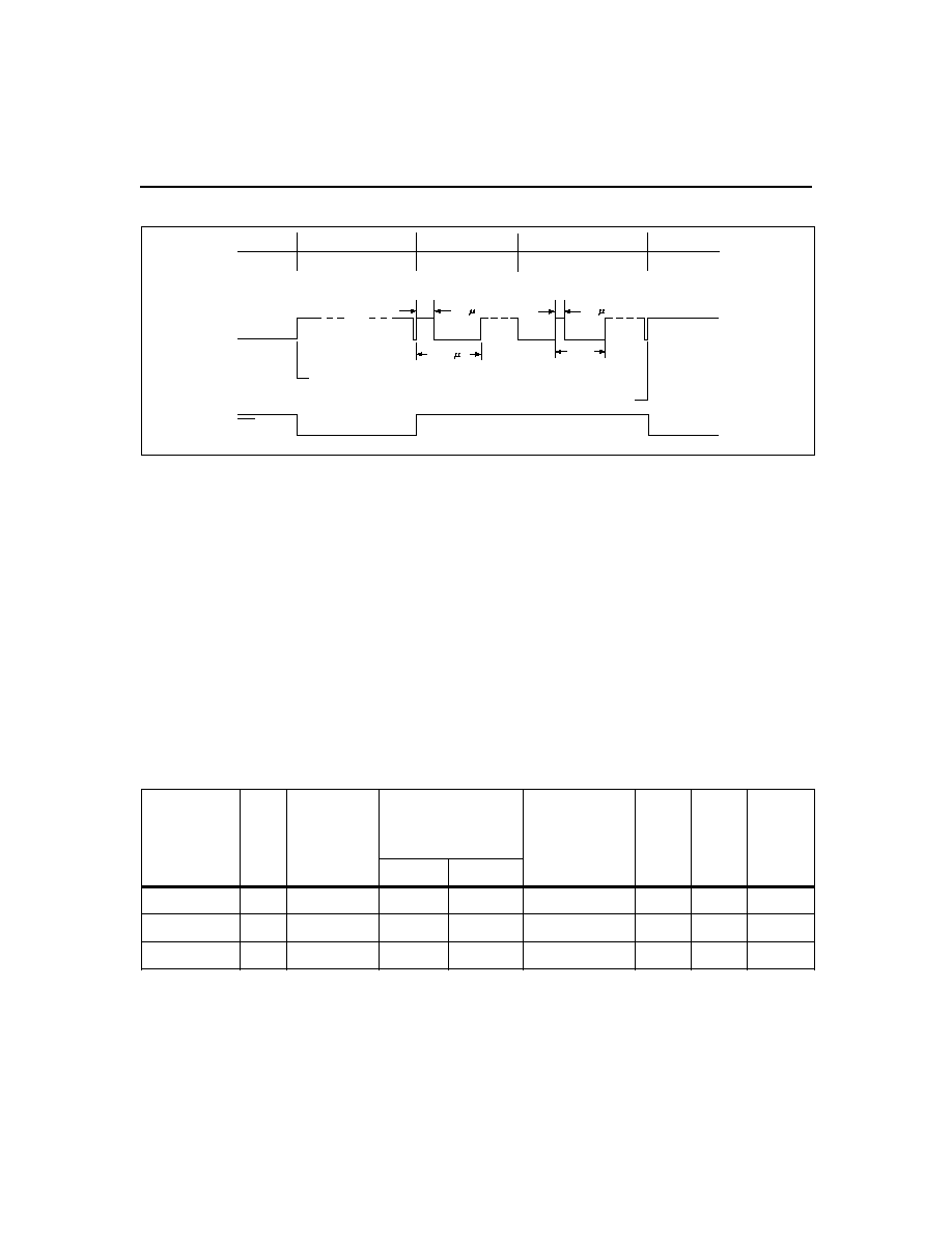
Starting A Charge Cycle
Either of two events starts a charge cycle (see Figure 4):
1. Application of power to V
CC
or
2. Voltage at the BAT pin falling through the maximum
cell voltage V
MCV
where
V
MCV
= 2V
±5%.
If the battery is within the configured temperature and
voltage limits, the IC begins fast charge. The valid bat-
tery voltage range is V
BAT
< V
MCV
. The valid tempera-
ture range is V
TS
> V
TCO
where
V
TCO
= 0.5
V
CC
±5%.
If the battery voltage or temperature is outside of these
limits, the IC pulse-trickle charges until the next new
charge cycle begins.
Fast charge continues until termination by one or more of
the five possible termination conditions:
n
Peak voltage detection (PVD)
n
Negative delta voltage (-
V)
n
Maximum voltage
n
Maximum temperature
n
Maximum time
4
bq2002/F
Corresponding
Fast-Charge
Rate
TM
Termination
Typical Fast-Charge
and Top-Off
Time Limits
(minutes)
Typical PVD
and -
V Hold-Off
Time (seconds)
Top-Off
Rate
Pulse-
Trickle
Rate
Pulse-
Trickle
Period
(ms)
bq2002
bq2002F
C/2
Mid
PVD
160
160
600
C/32
C/64
9.15
1C
Low
PVD
80
100
300
C/16
C/64
18.3
2C
High
-
V
40
40
150
Disabled
C/32
18.3
Notes:
Typical conditions = 25∞C, V
CC
= 5.0V.
Mid = 0.5 * V
CC
±5V
Tolerance on all timing is
±20%.
Table 1. Fast-Charge Safety Time/Hold-Off Table
TD2002F1.eps
Fast Charging
VCC = 0
Fast Charging
CC Output
LED
s
s
Charge initiated by application of power
Charge initiated by battery replacement
Pulse-Trickle
Top-Off
(optional)
286
See
Table 1
s
286
4576
Figure 4. Charge Cycle Phases

PVD and -
V Termination
There are two modes for voltage termination depending
on the state of TM. For -
V (TM = high), if V
BAT
is
lower than any previously measured value by 12mV
±3mV, fast charge is terminated. For PVD (TM = low or
mid), a decrease of 2.5mV
±2.5mV terminates fast
charge. The PVD and -
V tests are valid in the range
1V < V
BAT
< 2V.
Voltage Sampling
Voltage is sampled at the BAT pin for PVD and -
V ter-
mination once every 17s. The sample is an average of
voltage measurements taken 57
µs apart. The IC takes
32 measurements in PVD mode and 16 measurements
in -
V mode. The resulting sample periods (9.17 and
18.18ms, respectively) filter out harmonics centered
around 55 and 109Hz. This technique minimizes the ef-
fect of any AC line ripple that may feed through the
power supply from either 50 or 60Hz AC sources. Toler-
ance on all timing is
±20%.
Voltage Termination Hold-off
A hold-off period occurs at the start of fast charging.
During the hold-off time, the PVD and -
V terminations
are disabled. This avoids premature termination on the
voltage spikes sometimes produced by older batteries
when fast-charge current is first applied.
Maximum
voltage and temperature terminations are not affected
by the hold-off period.
Maximum Voltage, Temperature, and Time
Any time the voltage on the BAT pin exceeds the maxi-
mum cell voltage,V
MCV
, fast charge or optional top-off
charge is terminated.
Maximum temperature termination occurs anytime the
voltage on the TS pin falls below the temperature cut-off
threshold V
TCO
.
Maximum charge time is configured using the TM pin.
Time settings are available for corresponding charge
rates of C/2, 1C, and 2C. Maximum time-out termina-
tion is enforced on the fast-charge phase, then reset, and
enforced again on the top-off phase, if selected. There is
no time limit on the trickle-charge phase.
Top-off Charge
An optional top-off charge phase may be selected to
follow fast charge termination for 1C and C/2 rates.
This phase may be necessary on NiMH or other bat-
tery chemistries that have a tendency to terminate
charge prior to reaching full capacity. With top-off en-
abled, charging continues at a reduced rate after
fast-charge termination for a period of time selected
by the TM pin. (See Table 1.) During top-off, the CC
pin is modulated at a duty cycle of 286
µs active for
every 4290
µs inactive. This modulation results in an
average rate 1/16th that of the fast charge rate. Maxi-
mum voltage, time, and temperature are the only ter-
mination methods enabled during top-off.
Pulse-Trickle Charge
Pulse-trickle is used to compensate for self-discharge
while the battery is idle in the charger. The battery is
pulse-trickle charged by driving the CC pin active for a
period of 286
µs for every 18.0ms of inactivity for 1C and
2C selections, and 286
µs for every 8.86ms of inactivity
for C/2 selection. This results in a trickle rate of C/64
for the top-off enabled mode and C/32 otherwise.
TM Pin
The TM pin is a three-level pin used to select the
charge timer, top-off, voltage termination mode, trickle
rate, and voltage hold-off period options. Table 1 de-
scribes the states selected by the TM pin. The mid-
level selection input is developed by a resistor di-
vider between V
CC
and ground that fixes the voltage
on TM at V
CC
/2
± 0.5V. See Figure 4.
Charge Status Indication
A fast charge in progress is uniquely indicated when the
LED pin goes low. The LED pin is driven to the high-Z
state for all conditions other than fast charge. Figure 2
outlines the state of the LED pin during charge.
Charge Inhibit
Fast charge and top-off may be inhibited by using the
INH pin. When high, INH suspends all fast charge and
top-off activity and the internal charge timer.
INH
freezes the current state of LED until inhibit is re-
moved. Temperature monitoring is not affected by the
INH pin. During charge inhibit, the bq2002/F continues
to pulse-trickle charge the battery per the TM selection.
When INH returns low, charge control and the charge
timer resume from the point where INH became active.
Low-Power Mode
The IC enters a low-power state when V
BAT
is driven
above the power-down threshold (V
PD
) where
V
PD
= V
CC
- (1V
±0.5V)
Both the CC pin and the LED pin are driven to the
high-Z state. The operating current is reduced to less
than 1
µA in this mode. When V
BAT
returns to a value
below V
PD
, the IC pulse-trickle charges until the next
new charge cycle begins.
5
bq2002/F