 | ÐлекÑÑоннÑй компоненÑ: BQ2002EPN | СкаÑаÑÑ:  PDF PDF  ZIP ZIP |
Äîêóìåíòàöèÿ è îïèñàíèÿ www.docs.chipfind.ru
Features
®
Fast charge of nickel cadmium
or nickel-metal hydride batter-
ies
®
Direct LED output displays
charge status
®
Fast-charge termination by -
V,
maximum voltage, maximum
temperature, and maximum
time
®
Internal band-gap voltage ref-
erence
®
Optional top-off charge
®
Selectable pulse trickle charge
rates
®
Low-power mode
®
8-pin 300-mil DIP or 150-mil
SOIC
General Description
The bq2002E and bq2002G Fast-
Charge ICs are low-cost CMOS bat-
tery-charge controllers providing reli-
able charge termination for both NiCd
and NiMH battery applications. Con-
trolling a current-limited or con-
stant-current supply allows the
bq2002E/G to be the basis for a cost-
effective stand-alone or system-inte-
grated charger. The bq2002E/G inte-
grates fast charge with optional top-off
and pulsed- trickle control in a single
IC for charging one or more NiCd or
NiMH battery cells.
Fast charge is initiated on application
of the charging supply or battery re-
placement. For safety, fast charge is
inhibited if the battery temperature
and voltage are outside configured
limits.
Fast charge is terminated by any of
the following:
n
Peak voltage detection (PVD)
n
Negative delta voltage (-
V)
n
Maximum voltage
n
Maximum temperature
n
Maximum time
After fast charge, the bq2002E/G op-
tionally tops-off and pulse-trickles the
battery per the pre-configured limits.
Fast charge may be inhibited using
the INH pin.
The bq2002E/G may
also be placed in low-standby-power
mode to reduce system power con-
sumption.
T h e b q 2 0 0 2 E d i f f e r s f r o m t h e
bq2002G only in that a slightly dif-
ferent set of fast-charge and top-off
time limits is available. All differ-
ences between the two ICs are illus-
trated in Table 1.
1
NiCd/NiMH Fast-Charge Management ICs
bq2002E/G
TM
Timer mode select input
LED
Charging status output
BAT
Battery voltage input
V
SS
System ground
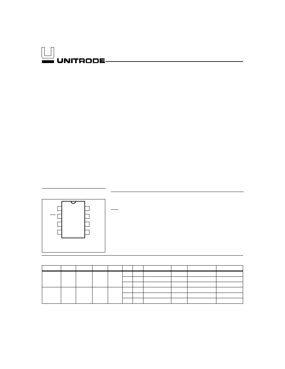
1
PN-200201.eps
8-Pin DIP or
Narrow SOIC
2
3
4
8
7
6
5
TM
LED
BAT
VSS
CC
INH
VCC
TS
TS
Temperature sense input
V
CC
Supply voltage input
INH
Charge inhibit input
CC
Charge control output
Pin Connections
Pin Names
2/99
bq2002E/G Selection Guide
Part No.
LBAT
TCO
HTF
LTF
-
V
PVD
Fast Charge
t
MTO
Top-Off
Maintenance
bq2002E 0.175
V
CC
0.5
V
CC
0.6
V
CC
None
C/2
200
None
C/32
1C
80
C/16
C/32
2C
40
None
C/32
bq2002G 0.175
V
CC
0.5
V
CC
0.6
V
CC
None
C/2
160
None
C/32
1C
80
C/16
C/32
2C
40
None
C/32
Pin Descriptions
TM
Timer mode input
A three-level input that controls the settings
for the fast charge safety timer, voltage ter-
mination mode, top-off, pulse-trickle, and
voltage hold-off time.
LED
Charging output status
Open-drain output that indicates the charging
status.
BAT
Battery input voltage
The battery voltage sense input. The input to
this pin is created by a high-impedance re-
sistor divider network connected between
the positive and negative terminals of the
battery.
V
SS
System ground
TS
Temperature sense input
Input for an external battery temperature
monitoring thermistor.
V
CC
Supply voltage input
5.0V
±
20% power input.
INH
Charge inhibit input
When high, INH suspends the fast charge in
progress.
When returned low, the IC re-
sumes operation at the point where initially
suspended.
CC
Charge control output
An open-drain output used to control the
charging current to the battery. CC switch-
ing to high impedance (Z) enables charging
current to flow, and low to inhibit charging
current. CC is modulated to provide top-off,
if enabled, and pulse trickle.
Functional Description
Figure 2 shows a state diagram and Figure 3 shows a
block diagram of the bq2002E/G.
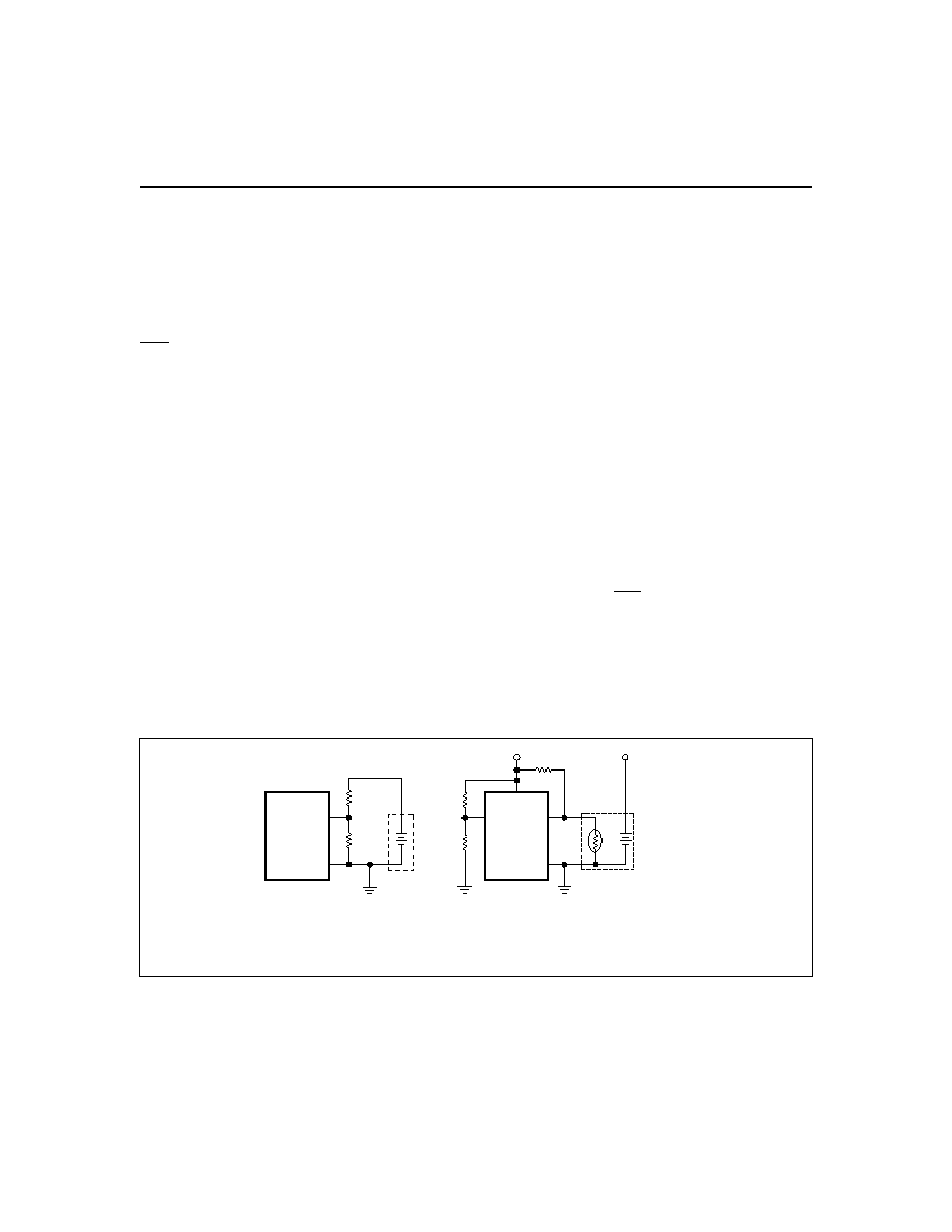
Battery Voltage and Temperature
Measurements
Battery voltage and temperature are monitored for
maximum allowable values. The voltage presented on
the battery sense input, BAT, should represent a
single-cell potential for the battery under charge. A
resistor-divider ratio of
RB1
RB2
= N - 1
is recommended to maintain the battery voltage within
the valid range, where N is the number of cells, RB1 is
the resistor connected to the positive battery terminal,
and RB2 is the resistor connected to the negative bat-
tery terminal. See Figure 1.
Note: This resistor-divider network input impedance to
end-to-end should be at least 200k
and less than 1 M
.
2
bq2002E/G
Fg2002E/G01.eps
bq2002E/G
BAT
VSS
N
T
C
bq2002E/G
VCC
VCC
PACK +
TS
VSS
BAT pin connection
Thermistor connection
TM
NTC = negative temperature coefficient thermistor.
RT
R3
R4
RB1
RB2
Mid-level
setting for TM
Figure 1. Voltage and Temperature Monitoring and TM Pin Configuration
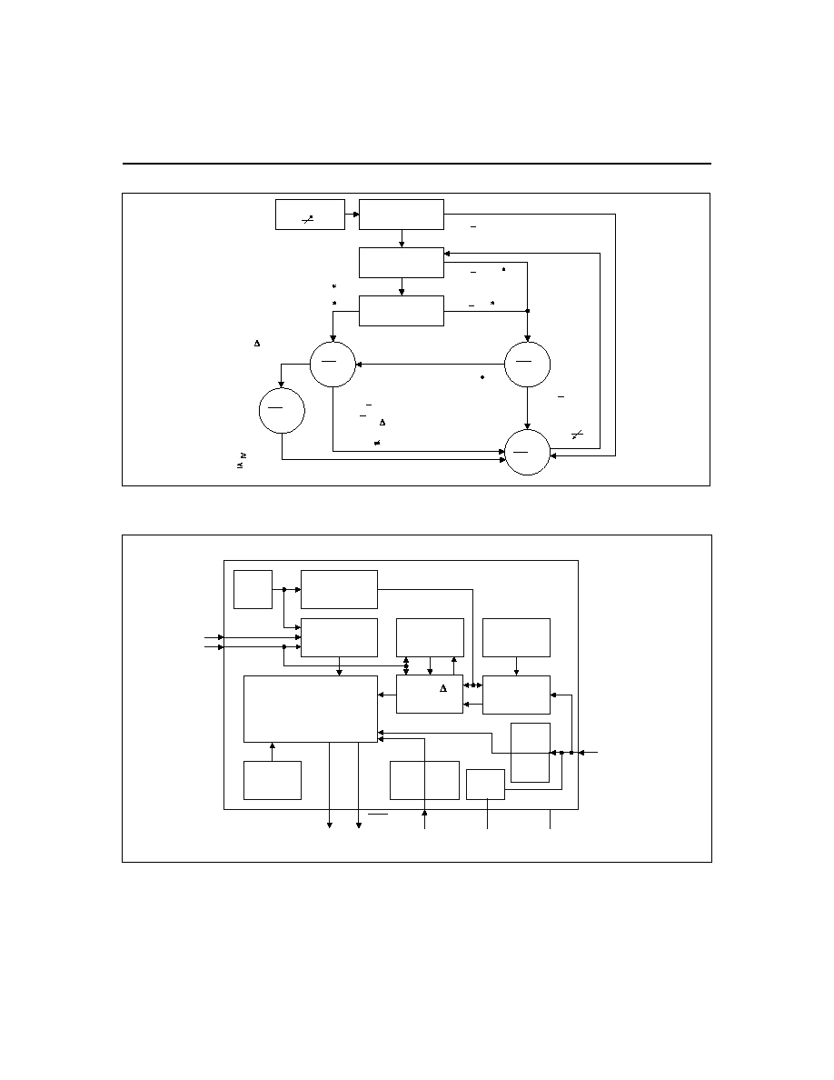
3
bq2002E/G
OSC
TM
CC
LED
VCC
VSS
BAT
INH
Clock
Phase
Generator
Timing
Control
Sample
History
A to D
Converter
MCV
Check
Power
Down
TS
Bd2002CEG.eps
Voltage
Reference
Power-On
Reset
TCO
Check
HTF
Check
LBAT
Check
Charge-Control
State Machine
PVD, - V
ALU
Figure 3. Block Diagram
Chip on
VCC 4.0V
Battery Voltage
too High?
Battery
Temperature?
Charge
Pending
Fast
LED =
Low
SD2002C.eps
Battery Voltage
too Low?
VBAT < 2V
VTS < 0.6
VBAT > 0.175
VBAT < 2V, and
VTS > VCC/2
VBAT
>
2V
Top-off
LED = Z
Trickle
LED =
Flash
Trickle
LED = Z
VBAT > 2V
VBAT 2V
VCC
VTS > 0.6 VCC
VCC,
0.175 VCC < VBAT
VCC
VBAT < 0.175
VBAT > 2V or
VTS < VCC/2 or
((PVD or - V or
Maximum Time Out)
and TM
Low)
VBAT
VTS
Maximum Time Out
2V or
VCC/2 or
(PVD or -
Maximum Time Out)
and TM = Low
V or
Figure 2. State Diagram
A ground-referenced negative temperature coefficient ther-
mistor placed near the battery may be used as a low-cost
temperature-to-voltage transducer. The temperature
sense voltage input at TS is developed using a resistor-
thermistor network between V
CC
and V
SS
. See Figure 1.
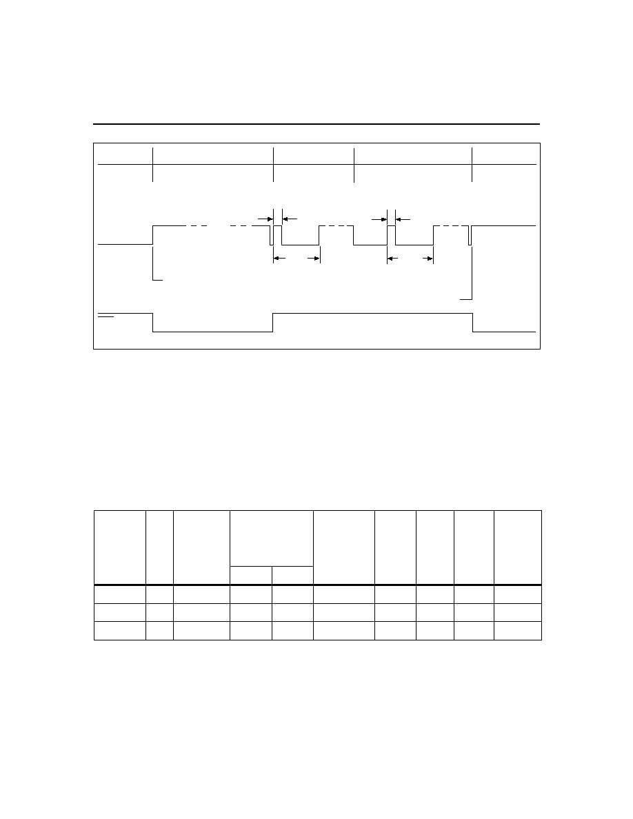
Starting A Charge Cycle
Either of two events starts a charge cycle (see Figure 4):
1. Application of power to V
CC
or
2. Voltage at the BAT pin falling through the maximum
cell voltage V
MCV
where
V
MCV
= 2V
±
5%.
If the battery is within the configured temperature and
voltage limits, the IC begins fast charge. The valid bat-
tery voltage range is V
LBAT
< V
BAT
< V
MCV
, where
4
bq2002E/G
Corre-
sponding
Fast-Charge
Rate
TM
Termination
Typical Fast-
Charge and
Top-Off
Time Limits
(minutes)
Typical PVD
and -
V
Hold-Off Time
(seconds)
Top-Off
Rate
Pulse-
Trickle
Rate
Pulse-
Trickle
Width
(ms)
Maximum
Synchro-
nized
Sampling
Period
(seconds)
bq2002E bq2002G
C/2
Mid
PVD
200
160
300
Disabled
C/32
73
18.7
1C
Low
PVD
80
80
150
C/16
C/32
37
18.7
2C
High
-
V
40
40
75
Disabled
C/32
18
9.4
Notes:
Typical conditions = 25°C, V
CC
= 5.0V
Mid = 0.5 * V
CC
±
0.5V
Tolerance on all timing is
±
12%.
Table 1. Fast-Charge Safety Time/Hold-Off/Top-Off Table
TD2002EG.eps
Fast Charging
VCC = 0
Fast Charging
CC Output
LED
Charge initiated by application of power
Charge initiated by battery replacement
Pulse-Trickle
Top-Off
(optional)
73ms
1.17s
1.17s
See Table 1
Figure 4. Charge Cycle Phases

V
LBAT
= 0.175
V
CC
±
20%
The valid temperature range is V
TS
> V
HTF
where
V
HTF
= 0.6
V
CC
±
5%.
If the battery voltage or temperature is outside of these
limits, the IC pulse-trickle charges until the next new
charge cycle begins.
If V
MCV
< V
BAT
< V
PD
(see "Low-Power Mode") when a
new battery is inserted, a delay of 0.35 to 0.9s is imposed
before the new charge cycle begins.
Fast charge continues until termination by one or more of
the five possible termination conditions:
n
Peak voltage detection (PVD)
n
Negative delta voltage (-
V)
n
Maximum voltage
n
Maximum temperature
n
Maximum time
PVD and -
V Termination
There are two modes for voltage termination, depending
on the state of TM. For -
V (TM = high), if V
BAT
is lower
than any previously measured value by 12mV
±
3mV, fast
charge is terminated. For PVD (TM = low or mid), a de-
crease of 2.5mV
±
2.5mV terminates fast charge. The PVD
and -
V tests are valid in the range 1V < V
BAT
< 2V.
Synchronized Voltage Sampling
Voltage sampling at the BAT pin for PVD and -
V termi-
nation may be synchronized to an external stimulus us-
ing the INH input. Low-high-low input pulses between
100ns and 3.5ms in width must be applied at the INH
pin with a frequency greater than the "maximum syn-
chronized sampling period" set by the state of the TM
pin as shown in Table 1. Voltage is sampled on the fal-
ling edge of such pulses.
If the time between pulses is greater than the synchro-
nizing period, voltage sampling "free-runs" at once every
17 seconds. A sample is taken by averaging together
voltage measurements taken 57
µ
s apart. The IC takes
32 measurements in PVD mode and 16 measurements
in -
V mode. The resulting sample periods (9.17 and
18.18ms, respectively) filter out harmonics centered
around 55 and 109Hz. This technique minimizes the ef-
fect of any AC line ripple that may feed through the
power supply from either 50 or 60Hz AC sources.
If the INH input remains high for more than 12ms, the
voltage sample history kept by the IC and used for PVD
and -
V termination decisions is erased and a new his-
tory is started. Such a reset is required when transition-
ing from free-running to synchronized voltage sampling.
The response of the IC to pulses less than 100ns in
width or between 3.5ms and 12ms is indeterminate. Tol-
erance on all timing is
±
12%.
Voltage Termination Hold-off
A hold-off period occurs at the start of fast charging.
During the hold-off time, the PVD and -
V terminations
are disabled. This avoids premature termination on the
voltage spikes sometimes produced by older batteries
when fast-charge current is first applied. Maximum
voltage and temperature terminations are not affected
by the hold-off period.
Maximum Voltage, Temperature, and Time
Any time the voltage on the BAT pin exceeds the maxi-
mum cell voltage,V
MCV
, fast charge or optional top-off
charge is terminated.
Maximum temperature termination occurs anytime the
voltage on the TS pin falls below the temperature cut-off
threshold V
TCO
where
V
TCO
= 0.5
V
CC
±
5%.
Maximum charge time is configured using the TM pin.
Time settings are available for corresponding charge
rates of C/2, 1C, and 2C. Maximum time-out termina-
tion is enforced on the fast-charge phase, then reset, and
enforced again on the top-off phase, if selected. There is
no time limit on the trickle-charge phase.
Top-off Charge
An optional top-off charge phase may be selected to
follow fast charge termination for 1C and C/2 rates.
This phase may be necessary on NiMH or other bat-
tery chemistries that have a tendency to terminate
charge before reaching full capacity. With top-off en-
abled, charging continues at a reduced rate after
fast-charge termination for a period of time selected
by the TM pin. (See Table 1.) During top-off, the CC
pin is modulated at a duty cycle of 73ms active for
every 1097ms inactive. This modulation results in an
average rate 1/16th that of the fast charge rate. Maxi-
mum voltage, time, and temperature are the only ter-
mination methods enabled during top-off.
Pulse-Trickle Charge
Pulse-trickle is used to compensate for self-discharge
while the battery is idle in the charger. The battery is
pulse-trickle charged by driving the CC pin active once
every 1.17s for the period specified in Table 1. This re-
sults in a trickle rate of C/32.
TM Pin
The TM pin is a three-level pin used to select the
charge timer, top-off, voltage termination mode, trickle
5
bq2002E/G