 | ÐлекÑÑоннÑй компоненÑ: BQ2007S- | СкаÑаÑÑ:  PDF PDF  ZIP ZIP |
Äîêóìåíòàöèÿ è îïèñàíèÿ www.docs.chipfind.ru
Features
Fast charging and conditioning of
NiCd and NiMH batteries
-
Precise charging independent
of battery pack number of cells
-
Discharge-before-charge on
demand
-
Pulse trickle charge
conditioning
-
Battery undervoltage and
overvoltage protection
Built-in 10-step voltage-based
charge status monitoring
-
Charge status display options
include seven-segment
monotonic bargraph and fully
decoded BCD digit
-
Display interface options for
direct drive of LCD or LED
segments
-
Charger state status
indicators for pending,
discharge, charge, completion,
and fault
-
Audible alarm for charge
completion and fault
conditions
Charge control flexibility
-
Fast or Standard speed
charging
-
Top-off mode for NiMH
-
Charge rates from
C
8
to 2C
(30 minutes to 8 hours)
Charge termination by:
-
Negative delta voltage (-
V)
-
Peak voltage detect (PVD)
-
Maximum voltage
-
Maximum time
-
Maximum temperature
High-efficiency switch-mode de-
sign
-
Ideal for small heat-sensitive
enclosures
24-pin, 300-mil SOIC or DIP
General Description
The bq2007 is a highly integrated
monolithic CMOS IC designed to pro-
vide intelligent battery charging and
charge status monitoring for stand-
alone charge systems.
The bq2007 provides a wide variety of
charge status display formats. The
bq2007 internal charge status moni-
tor supports up to a seven-segment
bargraph or a single BCD digit dis-
play. The bargraph display indicates
up to seven monotonic steps, whereas
the BCD digit counts in ten steps of
10% increments. The bq2007 output
drivers can direct-drive either an
LCD or LED display.
Charge action begins either by appli-
cation of the charging supply or by
replacement of the battery pack. For
safety, charging is inhibited until
battery temperature and voltage are
within configured limits.
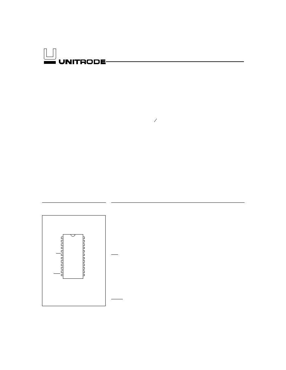
1
1
PN200701.eps
24-Pin Narrow DIP
or SOIC
2
3
4
5
6
7
8
24
23
22
21
20
19
18
17
9
10
16
15
11
12
14
13
SEGC/MSEL
SEGB
SEGA
LED1
LED2
INH
COM
ALARM
TM
VSEL
FAST
DCMD
SEGD/DSEL1
SEGE/DSEL2
SEGF/MULT
SEGG/QDSEL
MOD
VCC
VSS
DIS
TS
BAT
SNS
TCO
Fast-Charge IC
bq2007
Pin Connections
Pin Names
SEG
C
/
Display output segment C/
MSEL
driver mode select
SEG
B
Display output segment B
SEG
A
Display output segment A
LED
1
Charge status output 1
LED
2
Charge status output 2
INH
Charge inhibit input
COM
Common LED/LCD output
ALARM
Audio alarm output
TM
Timer mode select
VSEL
Voltage termination select
FAST
Fast charge rate select
DCMD
Discharge command
TCO
Temperature cutoff
SNS
Sense resistor input
BAT
Battery voltage
TS
Temperature sense
DIS
Discharge control
V
SS
System ground
V
CC
5.0V
±10% power
MOD
Modulation control
SEG
G
/
Display output segment G/
QDSEL
charge status display select
SEG
F
/
Display output segment F/
MULT
multi-cell pack select
SEG
E
/
Display output segment E/
DSEL
2
display select 2
SEG
D
/
Display output segment D/
DSEL
1
display select 1
9/96 B

The acceptable battery temperature range is set by an
internal low-temperature threshold and an external
high-temperature cutoff threshold. The absolute tem-
perature is monitored as a voltage on the TS pin with
the external thermistor network shown in Figure 2.
The bq2007 provides for undervoltage battery protection
from high-current charging if the battery voltage is less
than the normal end-of-discharge value. In the case of a
deeply discharged battery, the bq2007 enters the
charge-pending state and attempts trickle-current condi-
tioning of the battery until the voltage increases. Should
the battery voltage fail to increase above the discharge
value during the undervoltage time-out period, a fault
condition is indicated.
Discharge-before-charge may be selected to automatically
discharge the battery pack on battery insertion or with a
push-button switch. Discharge-before-charge on demand
provides conditioning services that are useful to correct or
prevent the NiCd voltage depression, or "memory" effect,
and also provide a zero capacity reference for accurate
capacity monitoring.
After prequalification and any required discharge-
before-charge operations, charge action begins until one of
the full-charge termination conditions is detected. The
bq2007 terminates charging by any of the following methods:
n
Negative delta voltage (-
V)
n
Peak voltage detect (PVD)
n
Maximum absolute temperature
n
Maximum battery voltage
n
Maximum charge time-out
The bq2007 may be programmed for negative delta
voltage (-
V) or peak voltage detect (PVD) charge
termination algorithms. The VSEL input pin selects -
V
or PVD termination to match the charge rate and
battery characteristics.
To provide maximum safety for battery and system,
charging terminates based on maximum temperature
cutoff (TCO), maximum cutoff voltage (MCV), and
maximum time-out (MTO). The TCO threshold is the
maximum battery temperature limit for charging. TCO
terminates charge action when the temperature sense
input voltage on the TS pin drops below the TCO pin
voltage threshold. MCV provides battery overvoltage
protection by detecting when the battery cell voltage
(V
CELL
= V
BAT
- V
SNS
) exceeds the VMCV value and ter-
minates fast charge, standard charge, or top-off charge.
The maximum time-out (MTO) termination occurs when
the charger safety timer has completed during the active
charge state.
The bq2007 indicates charge state status with an audio
alarm output option and two dedicated output pins with pro-
grammable display options. The DSEL12 inputs can select
one of the three display modes for the LED12 outputs.
Charger status is indicated for:
n
Charge pending
n
Charge in progress
n
Charge complete
n
Fault condition
Pin Descriptions
SEG
AG
Display output segments AG
State-of-charge monitoring outputs. QDSEL
input selects the bargraph or BCD digit dis-
play mode. See Table 3.
MSEL
Display driver mode select
Soft-programmed input selects LED or LCD
driver configuration at initialization.
When
MSEL is pulled up to V
CC
, outputs SEG
AG
are
LED interface levels; when MSEL is pulled
down to V
SS
, outputs SEG
AG
are LCD levels.
DSEL
1
DSEL
2
Display mode select 12
Soft-programmed inputs control the LED
1--2
charger status display modes at initialization.
See Table 2.
MULT
Fixed-cell pack select
Soft-programmed input is pulled up to V
CC
when charging multi-cell packs and is pulled
down to V
SS
for charging packs with a fixed
number of cells.
QDSEL
State-of-charge display select
The QDSEL input controls the SEG
AG
state-of-charge display modes. See Table 3.
LED
1
LED
2
Charger status outputs 12
Charger status output drivers for direct
drive of LED displays.
Display modes are
selected by the DSEL input. See Table 2.
INH
Charge inhibit input
When low, the bq2007 suspends all charge ac-
tions, drives all outputs to high impedance, and
assumes a low-power operational state. When
transitioning from low to high, a charge
cycle is initiated. See page 10 for details.
2
bq2007

COM
Common LCD/LED output
Common
output
for
LCD/LED
display
SEG
A--G
. Output is high-impedance during
initialization
to
allow
reading
of
soft-programmed
inputs
DSEL
1
,
DSEL
2
,
MSEL, MULT, and QDSEL.
ALARM
Audio output
Audio alarm output.
TM
Timer mode select
TM is a three-level input that controls the set-
tings for charge control functions. See Table 5.
VSEL
Voltage termination select
This
input
switches
the
voltage
detect
sensitivity. See Table 5.
FAST
Fast charge rate select
The FAST input switches between Fast and
Standard charge rates. See Table 4.
DCMD
Discharge command
The DCMD input controls the discharge-
before-charge function. A negative-going
pulse initiates a discharge action. If DCMD
is connected to V
SS
, automatic discharge-
before-charge is enabled. See Figure 3.
TCO
Temperature cut-off threshold input
Minimum allowable battery temperature-
sensor voltage. If the potential between TS
and SNS is less than the voltage at the TCO
input, then any fast charging or top-off
charging is terminated.
SNS
Sense resistor input
SNS controls the switching of MOD output based
on an external sense resistor. This provides the
lower reference potential for the BAT pin and the
TS pin.
BAT
Battery voltage input
Battery voltage sense input referenced to SNS
for the battery pack being charged. This resis-
tor divider network is connected between the
positive and the negative terminals of the
battery. See Figure 1.
TS
Temperature sense input
Input referenced to SNS for battery tem-
perature monitoring negative temperature
coefficient (NTC) thermistor.
DIS
Discharge control
DIS is a push-pull output that controls an
external transistor to discharge the battery
before charging.
V
SS
Ground
V
CC
V
CC
supply input
MOD
Current-switching control output
Push/pull output that controls the charging
current to the battery. MOD switches high to
enable current flow and low to inhibit current
flow.
Functional Description
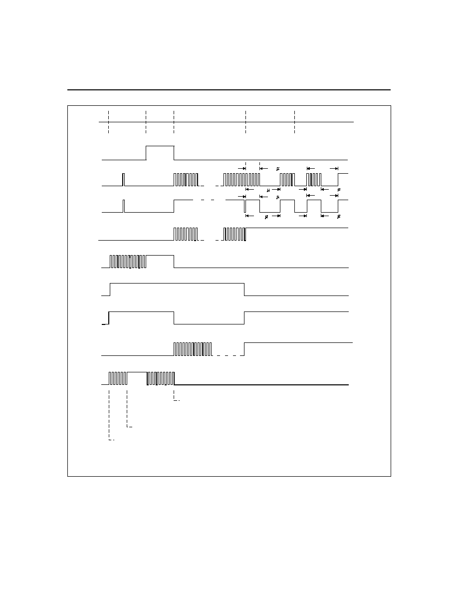
Figure 1 illustrates charge control and display status
during a bq2007 charge cycle. Table 1 summarizes the
bq2007 operational features. The charge action states
and control outputs are given for possible input
conditions.
Charge Action Control
The bq2007 charge action is controlled by input pins
DCMD, VSEL, FAST, and TM. When charge action is
initiated, the bq2007 enters the charge-pending state,
checks for acceptable battery voltage and temperature,
and performs any required discharge-before-charge
operations. DCMD controls the discharge-before-charge
function, and VSEL, FAST, and TM select the charger
configuration. See Tables 4 and 5.
During charging, the bq2007 continuously tests for
charge termination conditions: negative delta voltage,
peak voltage detection, maximum time-out, battery
over-voltage, and high-temperature cutoff. When the
charge state is terminated, a trickle charge continues to
compensate for self-discharge and maintain the fully
charged condition.
Charge Status Indication
Table 2 summarizes the bq2007 charge status display
indications. The charge status indicators include the
DIS output, which can be used to indicate the discharge
state, the audio ALARM output, which indicates charge
completion and fault conditions, and the dedicated
status outputs, LED
1
and LED
2
.
3
bq2007
4
bq2007
Fast Charging
Top-Off
(Optional)
TD200701.eps
Dis-
charge
(Optional)
Charge
Pending
(Pulse-Trickle)
DIS
MOD
MOD
Mode 1, LED2 Status Output
Charge initiated. Battery outside temperature/voltage limits.
or
Battery discharged to VEDV or battery within
temperature/voltage limits. (Discharge-before-charge not
qualified by temperature.)
Pulse-Trickle
(Switching
Configuration)
(External
Regulation)
Mode 1, LED1 Status Output
Mode 2, LED2 Status Output
Mode 2, LED1 Status Output
Mode 3, LED2 Status Output
260 s
2080 s
260 s
2080 s
260 s
Note
260 s
Note
Note: See Table 4 for pulse-trickle period.
Mode 3, LED1 Status Output
Low-voltage fault: Battery voltage less than VEDV for under-voltage time-out.
Figure 1. Example Charging Action Events
Outputs LED
12
have three display modes that are
selected at initialization by the input pins DSEL
1
and
DSEL
2
. The DSEL
1
and DSEL
2
input pins, when pulled
down to V
SS
, are intended for implementation of a
simple two-LED system. LED
2
indicates the precharge
status (i.e., charge pending and discharge) and LED
1
indi-
cates the charge status (i.e., charging and completion).
DSEL
1
pulled up to V
CC
and DSEL
2
pulled down to V
SS
mode is for implementation of a single tri-color LED such
that discharge, charging, and completion each have a unique
color. DSEL
1
pulled down to V
SS
and DSEL
2
pulled up to
V
CC
allows for fault status information to be displayed.
Audio Output Alarm
The bq2007 audio alarm output generates an audio tone
to indicate a charge completion or fault condition. The
audio alarm output is a symmetrical duty-cycle AC sig-
nal that is compatible with standard piezoelectric alarm
elements. A valid battery insertion is indicated by a sin-
gle high-tone beep of
1
2
-second typical duration.
The
charge completion and fault conditions are indicated by
a 9.5- to 15-second high-tone sequence of
1
2
-second typi-
cal duration at a 2-second typical repetition rate.
Charge Status Monitoring
The bq2007 charge status monitor may display the bat-
tery voltage or charge safety timer as a percentage of
the full-charged condition. These options are selected
with the MULT soft-programmed input pin.
When MULT is pulled down to V
SS
, the battery charge
status is displayed as a percentage of the battery
voltage, and the single-cell battery voltage at the BAT
pin is compared with internal charge voltage reference
thresholds.
When V
BAT
is greater than the internal
thresholds of V
20
, V
40
, V
60
, or V
80
, the respective 20%,
40%, 60%, or 80% display outputs are activated. The
b a t t e r y v o l t a g e d i r e c t l y i n d i c a t e s 2 0 % ch a r g e
increments, while the 10% charge increments use a
timer that is a function of the charge safety timer.
When MULT is pulled down to V
SS
and when V
BAT
exceeds V
20
during charging, the 20% charge indication
is activated and the timer begins counting for a period
equal to
1
64
to
1
32
of the charge safety time-out period.
When the timer count is completed, the 30% charge
indication is activated. Should V
BAT
exceed V
40
prior to
the timer count completion, the charge status monitor
activates the 30% and 40% indications. This technique
5
bq2007
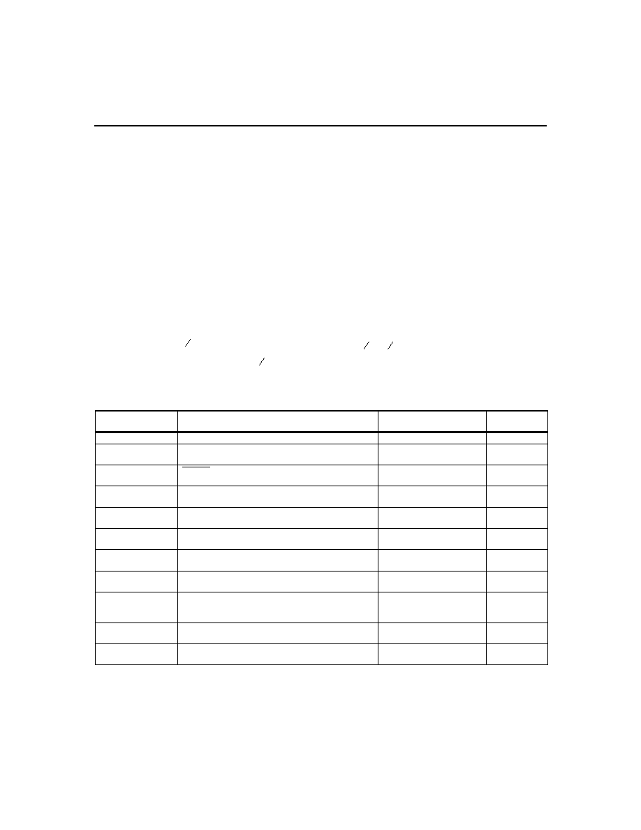
Charge Action
State
Conditions
MOD Output
DIS Output
Battery absent
V
CC
applied and V
CELL
V
MCV
Trickle charge per Table 4
Low
Charge initiation
V
CC
applied or V
CELL
drops
from
V
MCV
to < V
MCV
-
Low
Discharge-before-
charge
DCMD high-to-low transition or to V
SS
on charge
initiation and V
EDV
< V
CELL
< V
MCV
Low
High
Charge pending
Charge initiation occurred and V
TEMP
V
LTF
or
V
TEMP
V
TCO
or V
CELL
< V
EDV
Trickle charge per Table 4
Low
Fast charging
Charge pending complete and FAST = V
CC
Low if V
SNS
> 250mV;
high if V
SNS
< 200mV
Low
Standard charging
Charge pending complete and FAST = V
SS
Low if V
SNS
> 250mV;
high if V
SNS
< 200mV
Low
Charge complete
-
V termination or V
TEMP
< V
TCO
or PVD
0 to
-3mV/cell or maximum time-out or V
CELL
> V
MCV
-
-
Top-off pending
VSEL = V
CC
, charge complete and V
TEMP
V
LTF
or V
TEMP
V
TCO
or V
CELL
< V
EDV
Trickle charge per Table 4
Low
Top-off charging
VSEL = V
CC
and charge complete and
time-out not exceeded and V
TEMP
> V
TCO
and
V
CELL
< V
MCV
Activated per V
SNS
for
73ms of every 585ms
Low
Trickle charging
Charge complete and top-off disabled or
top-off complete or pending
Trickle charge per Table 4
Low
Fault
Charge pending state and charge pending
time-out (t
PEND
) complete
Trickle charge per Table 4
Low
Definitions:
V
CELL
= V
BAT
- V
SNS
; V
MCV
= 0.8 * V
CC
; V
EDV
= 0.262 * V
CC
or 0.4 * V
CC
; V
TEMP
= V
TS
- V
SNS
;
V
LTF
= 0.5 * V
CC
.
Table 1. bq2007 Operational Summary